3D Printing Tolerances:
SettheRightClearance
A part that fits on screen can still jam or wobble once it is printed. Tolerances close that gap. This guide covers the full method, from the causes of error to the final print. OrcaSlicer's built-in Tolerance Test makes the same process faster.
Where the Gap Between Your Design and Your Print Comes From
Four effects move a printed dimension away from the number in your model file. Their weight changes with part size, material, and printer.
Design clearance
The gap you draw between two mating parts sets the starting fit. Too little and the parts bind; too much and they rattle.
CAD PhaseExtrusion
Over-extrusion thickens walls and shrinks holes. Calibrate flow first for a consistent baseline.
Flow Ratio CalculatorThermal shrinkage
Plastic contracts as it cools. The effect is stronger for specific materials like ABS or ASA.
Material CoolingHole roundness
Round holes often come out smaller or polygonal. Hole correction settings in OrcaSlicer address this.
Mechanical FitsStarting Clearances for Three Fit Types
Use these values as starting points for a 0.4 mm nozzle. Treat each value as the first print in a test rather than a final answer.
*Note: Values assume a well-tuned printer. Confirm the final value with the fit test in the next section.
| Fit type | What it does | Starting clearance (per side) |
|---|---|---|
| Loose fit | Parts move freely with no binding, such as lids, hinges, and guides | 0.3–0.5 mm |
| Sliding fit | A pin or shaft turns or slides with light resistance | 0.15–0.25 mm |
| Press fit | A peg is pushed into its hole and held by friction | ≤ 0 mm |
Run a Six-Hole Fit Test
A fit test prints a set of holes at stepped sizes, each with a matching peg, so one print shows which clearance works for your specific setup.
Method A: Use the built-in Tolerance Test
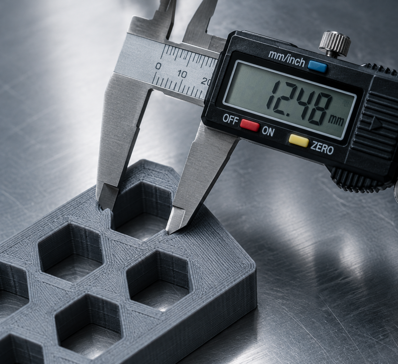
OrcaSlicer includes a Tolerance Test with six hex holes. Open the Calibration menu, choose Tolerance Test, and print it with your intended material and profile.
Method B: Build your own test
Use any simple design tool to make a block with six holes at stepped diameters, plus a separate peg for each hole. Print it with your normal settings.
Print test with target material and profile.
Let the print cool fully before measuring.
Measure each hole/peg with digital calipers.
Record Sheet
| Hole No. | Design size (mm) | Measured size (mm) | Peg fit | Notes |
|---|---|---|---|---|
| 01 | ||||
| 02 | ||||
| 03 | ||||
| 04 | ||||
| 05 | ||||
| 06 |
Correct Hole Size and Roundness
Two slicer settings target the two most common causes of size error. Enable one at a time and reprint your test.
Precise Wall
Tightens the overlap between outer and inner walls. Use it for thin ribs, thin pegs, and any part whose size is set mainly by its walls. This prevents the outer perimeter from bulging beyond the design path.
Polyholes
Adjusts the toolpath for round holes so they come out round instead of polygonal. Use it for holes that must take a pin, shaft, or bearing. It compensates for the tendency of circular paths to shrink inward.
Adjust for Your Material
PETG
Can ooze and string, adding small blobs to holes. Check retraction and flow before increasing clearance.
Read PETG guideABS and ASA
These materials shrink more as they cool. Allow more clearance on long features.
Read ASA guide
Common Failures and Fixes
| What you see | Likely cause | What to change |
|---|---|---|
| Pegs bind in every hole | Clearance too small or thin extrusion | Increase clearance, then recheck flow |
| Pegs rattle in every hole | Clearance too large or high extrusion | Reduce clearance, then recheck flow |
| Round holes come out polygonal | Hole roundness not corrected | Enable Polyholes and reprint test |
| Holes measure smaller than designed | Over-thick walls or high extrusion | Recheck flow, try Precise Wall |
| Fit correct in test but wrong on part | Orientation/wall count difference | Match test orientation to part |
| Mating faces do not seat flat | Warping or first-layer squish | Fix adhesion and check bed level |
| Flexible TPU parts loosen | Material gives under pressure | Measure after relaxation, loosen clearance |
Frequently Asked Questions
How much clearance should I design in?
Start from the table in section 3, then set the final value from your own fit test. The right number depends on your printer, material, and part.
Do I need OrcaSlicer to test tolerances?
No. Print a set of holes and pegs with your normal settings, then measure them with calipers. OrcaSlicer's Tolerance Test just makes the process faster.
Why do my holes come out smaller than designed?
Usual causes are over-extrusion, thick walls, and polygon-shaped holes. Calibrate flow first, then try Precise Wall and Polyholes.
Does one clearance value work for every material?
No. PLA, PETG, ABS, ASA, and TPU behave differently, so run the fit test on each material you print.
Put the Numbers to Work on Your Next Print
Calculate the shrinkage for your material, then confirm the clearance with a fit test before you print the part you need.
Stop guessing and start measuring for perfect fits every time.