Infill Pattern and Density:
How to Choose Strength Without Wasting Print Time
Infill is the material printed inside a part's outer walls. For a decorative piece it barely affects anything. For a bracket, clip, or holder that carries load, the pattern, the density, and the wall count all work together. This guide shows how to pick them and how to check your choice on a real part.
When infill decides strength, and when walls do
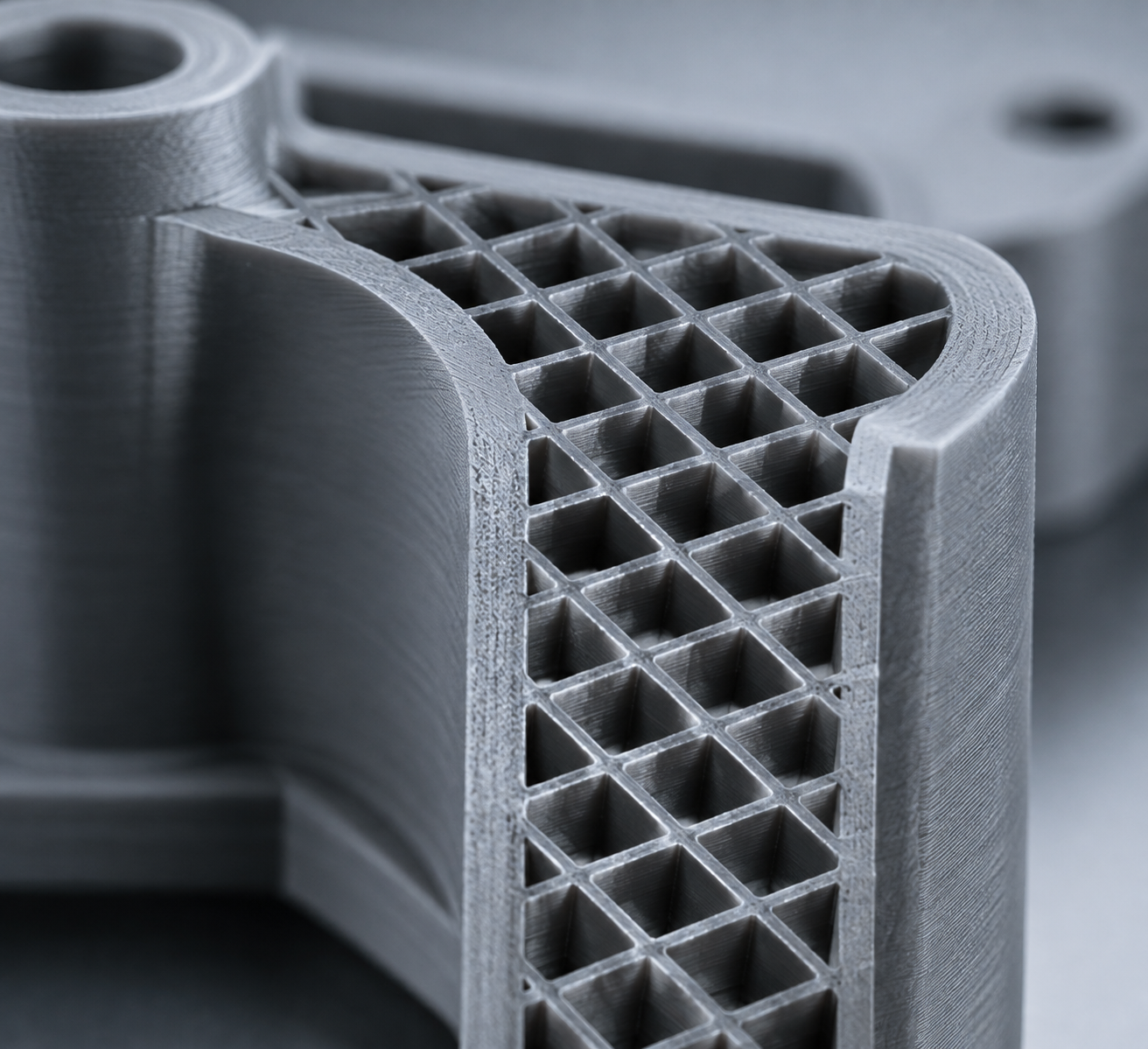
A part's load travels through its outer walls first. Infill mostly supports those walls and keeps the inside of thicker sections from collapsing under compression. That is why two parts with the same infill can behave very differently. A thin shell that bends under load depends on its walls and top layers. A thick block that gets squeezed depends on its infill.
Infill matters most: thick sections, parts that get compressed, and parts that are mostly interior volume.
Walls matter most: thin parts, parts loaded in bending, and parts where a crack would start at a surface.
Top and bottom layers matter most: flat parts with a load on the face, such as plates, lids, and panels.
Infill patterns compared
The pattern sets how the infill lines run inside the part. Each pattern trades stiffness, load behavior, and print time differently. Think of the pattern as the skeleton inside the walls: the question is which direction that skeleton has to resist.
Lines
Fast prints and flat panels
Parallel lines are strong along their length and weaker across them. Generally the fastest pattern to print.
Grid
General-purpose parts
Lines cross at right angles, so stiffness is more even than with Lines. Fast to print.
Triangles
Brackets and shear loads
Triangular cells resist shifting in several directions. Generally slower to print than Grid.
Cubic
Multi-directional loads
Interlocking 3D cells spread the load across all three axes. Moderate print time.
Gyroid
Even stiffness in all axes
Continuous curved paths give fairly even stiffness in every direction. Generally slower to print than Grid.
Honeycomb
High in-plane stiffness
Hexagonal cells give even in-plane stiffness. Generally slower to print than Grid.
Which pattern is strongest?
No pattern is strongest for every load. Gyroid is a common choice when a part is loaded from several directions and you want stiffness that does not depend on direction. When a part has one known load direction, a pattern whose strong lines run along that direction can outperform a generic pattern. If the part matters, print two versions and compare them.
How much density to use for each part
Density is the share of solid material inside the infill area. Set it by what the part does, then confirm the value on a test print.
Decorative parts
Nothing is loaded. Use a low density, enough to keep the print stable and support the top surface. Spend your effort on surface quality instead.
Functional parts
Parts that carry load need walls and top layers before density. Raise density only when a test shows the failure is inside the part, not at its walls.
Bolt holes and inserts
Add walls and solid top and bottom layers around the hole rather than raising density across the whole part. Local reinforcement usually costs less print time.
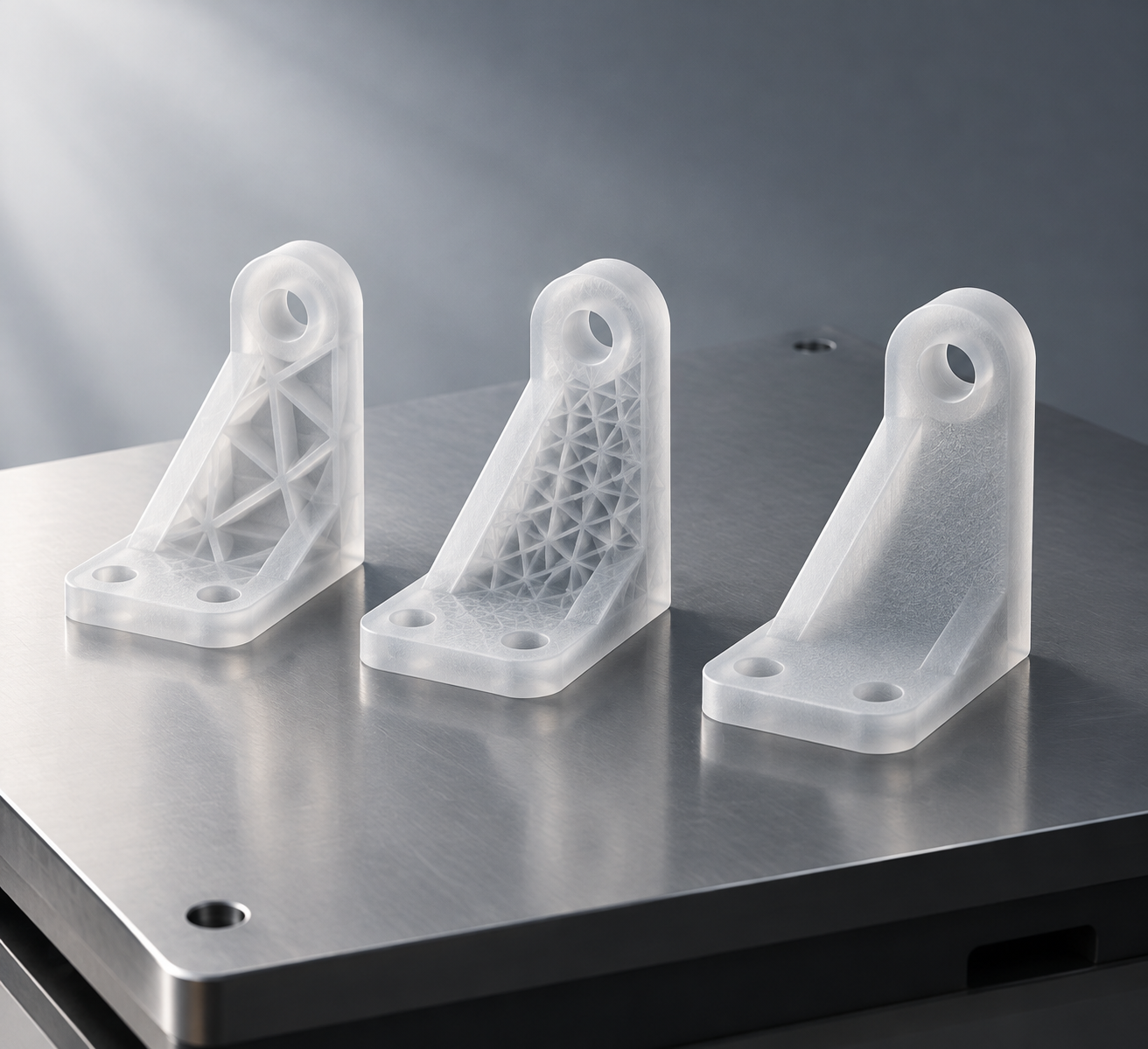
Density values are not universal. Use the test method in the final section to find the lowest density that passes for your part.
Walls and top layers: get stiffness before you add infill
Wall count and top and bottom thickness often change a part more than infill does, because they sit where bending and surface loads are highest. For load-bearing parts, a practical starting range is 2 to 3 walls and 0.8 to 1.0 mm of top and bottom thickness.
- 01
Walls
Increase the wall count before density when the part bends or cracks at its surface.
- 02
Top and bottom layers
Thicken them for plates, lids, and any part with a flat face under load.
- 03
Layer splits
When a part separates between layers, check adhesion and wall settings before you change infill.
Sandwich Mode: when an extra inner wall helps
Sandwich Mode, shown in Orca Slicer as alternate extra wall, adds an extra inner wall every other layer. The wall structure becomes stiffer than with standard walls, and it costs less print time than doubling every wall.
Use it when
- A thin-walled functional part failed at the bond between its walls and infill.
- A part must stay light but rigid in its walls.
Know the trade-offs
- It adds print time and material compared with standard walls.
- It is a wall setting. It does not replace density for parts that are compressed.
- Check the surface finish and fit on a sample before you use it on a finished part.
A step-by-step method for choosing settings
Note the loads on paper, follow the steps, then read the print time your slicer reports.
Describe the load
Write down where the part is held, where force is applied, and whether it bends or compresses.
Decide strength source
Thin walls point to walls/top layers. Thick sections under compression point to infill.
Choose a pattern
Single direction favors Lines/Grid. Multi-direction favors Gyroid/Cubic.
Set density
Start low for decorative. Apply walls-first for functional. Reinforce holes locally.
Set walls/top layers
Begin at 2-3 walls and 0.8 to 1.0 mm of top and bottom thickness.
Check print time
Slice and compare. If density adds too much time, use walls instead.
Test a sample
Print and load until failure. Change the setting that matches the break location.
Workflow Summary
Where Orca Slicer fits in this workflow
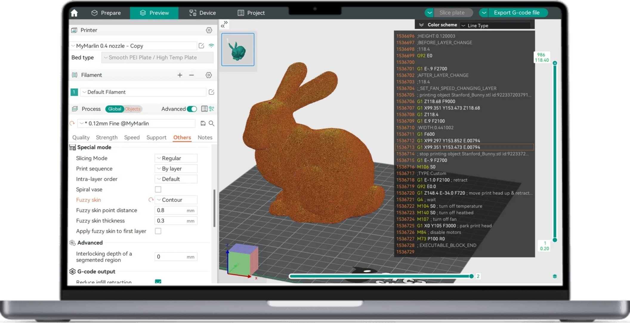
Orca Slicer groups the infill, wall, and Sandwich Mode settings under a Strength tab in its parameter panel, so you can adjust strength settings without digging through expert options. The panel has three visibility modes—Simple, Advanced, and Developer—so beginners see fewer options and you can expand the list as you learn.
Slice each version of the part in Orca Slicer and compare the estimated print times before you print. Orca Slicer is free and open source, and its releases are published on GitHub.
Check your choice with a test part
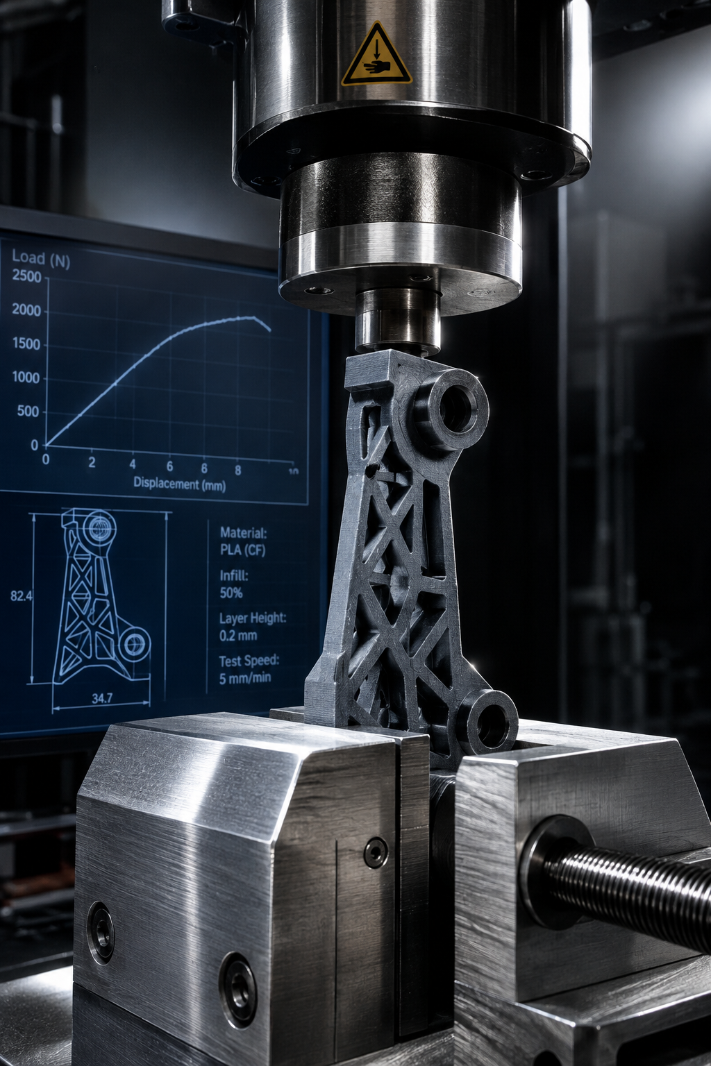
A test part shows what your settings actually do. Print the same part twice, changing one setting between versions, such as wall count or density. Load both versions the same way and note where each one fails.
- 1.
Print the part in both versions.
- 2.
Load each version until it fails, using the same weight, lever, or grip.
- 3.
Record where the break starts: at a wall, between layers, around a hole, or inside the infill.
- 4.
Change the setting that matches the failure point. Use walls for surface failures, density for failures inside.
- 5.
Keep the lowest-cost version that passes your load.
Common questions about infill
Is 100% infill always the strongest option?
Does higher infill density make a part stronger in every direction?
What is the strongest infill pattern?
What is Sandwich Mode in Orca Slicer?
Why did my part break at the wall even though the infill is dense?
Keep Reading
PLA filament guide
How PLA behaves and how to set it up for everyday prints.
PETG filament guide
How PETG behaves and when it suits load-bearing parts.
Carbon fiber filament guide
How carbon fiber filaments behave and what to set for stiff parts.
Max volumetric speed calculator
Estimate the flow limit that affects how fast dense infill can print.