Why the Bottom of a Print Flares Out
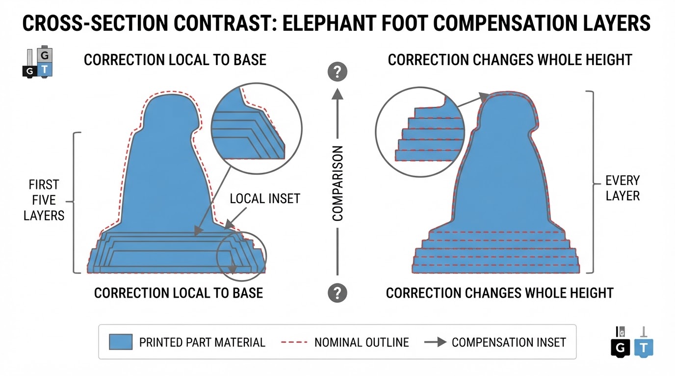
Elephant foot is the bulge that forms around the bottom edge of a print. The first layer is pressed into the build plate, and pressing material against a surface does not just flatten it — it also spreads it sideways. Whatever cannot go down goes outward. A warm bed keeps the bottom layers soft while that pressure is applied, so the lower edge settles slightly wider than the walls above it.
Most people meet elephant foot as a fit problem rather than a visual one. A part that should slide into a recess catches on its base. Printed holes and pins that were designed with a small clearance only work above the flare. Stacked parts rock on a lip that should not exist. If you measure the same feature at the base and higher up, the difference is your elephant foot.
It helps to separate elephant foot from other first-layer defects. Random blobs, a rough surface, or a wavy edge point to Z-offset, leveling, or flow problems. Elephant foot is dimensional and consistent: the base is oversized around the full perimeter, and it returns to the intended dimension a short distance up the part.
How Orca Slicer Compensates for Elephant Foot
Orca Slicer's approach is to correct the flare at its source rather than hide it after the fact. The first-layer controls deliberately pull the bottom of the part inward, so the finished base lands on the dimension you modeled instead of the dimension the squish produced.
The mechanism described in the site's published first-layer recipe is First Layer Expansion used as a negative value. Instead of letting the first layer spread, you shrink it by a controlled offset. The same recipe sets first-layer flow slightly below full — a 95–98% band — so there is less excess material in the base to begin with.
That compensation is one part of a wider first-layer reliability stack in Orca Slicer, alongside live Z-offset adjustment, first-layer speed and temperature targets, Mouse Ear Brims, Adaptive Bed Mesh, brim and raft options, and plate-type presets. The published recipe is explicit that this is a starting point rather than a universal setting: it reports elephant foot removed with a First Layer Expansion of about −0.2 to −0.3 mm and first-layer flow in the 95–98% band. Those values depend on your plate, your filament, and how much squish your profile already uses. Treat them as a place to begin measuring, not as a number to copy blindly.
Tune It With a Test Print
Elephant foot compensation is a measured loop, not a one-time checkbox. The fastest version of that loop is a coupon that is cheap to print and easy to measure.
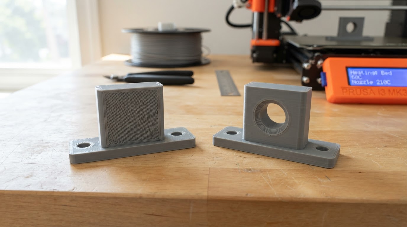
Print a simple calibration coupon — a small cube or a short stepped block — with the same filament, plate, and profile you use for real parts. First-layer behavior is what you are testing, so any other change contaminates the result.
Let the coupon cool completely. Then measure the base and the wall above the flare with digital calipers, on all four sides and in both axes. The flare is usually uniform. A base that is wider in one direction than another points at leveling or mesh rather than at the compensation value.
Change one thing at a time. Step the First Layer Expansion toward a more negative value and compare the same measurement after each reprint. When the base and the wall agree within your tolerance, you have your working value. If the base starts coming out narrower than the wall, you have gone past the correct setting, so back off one step.
The published recipe provides reference values you can start from:
Setting | Published starting recipe |
|---|---|
First layer speed | up to 20 mm/s |
Nozzle temperature | +5–10 °C over normal |
Bed temperature | +5 °C (PLA example: 215 °C / 60 °C) |
First Layer Expansion | −0.2 to −0.3 mm |
First-layer flow | 95–98% |
Keep the coupon and its measurements. When you change plate type or filament, rerun the same measurement before committing to a long print.
First-Layer Settings That Change the Result
Three settings decide how much flare you have to compensate for in the first place.
Speed. A slow first layer gives the extrusion time to bond instead of spreading, and the published recipe keeps first-layer speed at or below 20 mm/s.
Temperature. A slightly hotter nozzle and bed improve adhesion and reduce the amount of squish you need. The recipe adds 5–10 °C to the nozzle over your normal printing temperature and 5 °C to the bed; for PLA the example is 215 °C nozzle and 60 °C bed.
Flow. First-layer flow in the 95–98% band reduces the volume of material pressed sideways at the bottom.
Below those three, the plate and the mesh matter just as much. Orca Slicer exposes live Z-offset adjustment and Adaptive Bed Mesh, and a G29 or Klipper bed-mesh routine can live in the machine's start G-code, which keeps a printer profile portable between machines. Plate type changes how much squish you want: a smooth PEI sheet generally wants more than a textured one, which is why plate-specific presets — saved as a Plate Preset — are worth keeping instead of re-deriving the first layer every time you swap sheets.
Brims and Elephant Foot Compensation
The interaction most people miss is the brim. A brim is anchored to the same first layer you just shrank, so heavy compensation can leave a visible gap between the brim and the part, or a thin, blade-like edge tucked under it.
That does not make the brim useless. Mouse Ear Brims are a named Orca Slicer feature that adds material only where corner lift starts, which makes them easier to combine with aggressive first-layer compensation than a full brim. For small parts, the published guidance is a 4–6 line brim to stop corner lift.
After you change the expansion value, inspect the brim attachment on the coupon. If a gap appears, tune the brim settings rather than reverting the compensation. Raising first-layer flow to reattach the brim works against the reason you enabled compensation in the first place, because it puts material back into the base.
Verify Dimensional Accuracy Properly
Compensation is only proven by measurement, and one measurement is not verification.
Measure the base and a point clearly above the flare. Those two numbers should match the modeled dimension. An oversized reading at the bottom means the compensation is still too weak; a base narrower than the wall means it is too strong.
Measure at more than one height. Checking the very bottom edge and one step above it tells you whether the flare was flattened or merely pushed upward along the wall.
Run a fit test. If the part is meant to mate with something, print the mating feature — a recess, a pin, a lid — using the tuned profile and check the clearance. That is the outcome the setting exists to fix.
Repeat the coupon once. Two similar measurements from two prints of the same profile tell you the setting is stable. A difference between them points at inconsistent squish, bed temperature, or adhesion rather than at the compensation value itself.
If you run more than one printer or more than one plate, verify each machine-and-plate pair. Mixed-plate setups fail here more often than anywhere else, because one compensated profile copied across mismatched hardware produces different flare on every machine.
Common Mistakes and Trade-offs
Over-compensating. Too much negative expansion creates an undercut: the base becomes smaller than the walls above it. Press fits loosen, the bottom edge looks chamfered inward, and a new fit problem replaces the old one.
Using compensation as a calibration substitute. If the Z-offset is wrong, the bed mesh is stale, or the first layer is over-extruding, compensation hides the symptom while the rest of the print stays off. Fix the cause, then compensate for the flare that remains.
Ignoring the plate. Swapping a textured sheet for a smooth one changes squish — and therefore flare — without any other setting changing. Plate presets exist for exactly this reason.
Assuming a value travels. A setting that works on one filament can be wrong on the next, because different materials squash differently. Re-measure after a material change instead of trusting the old number.
Compensating for a global dimension error. Elephant foot compensation acts on the bottom of the part. If the whole print measures oversized, the cause is flow or motion calibration, not the first layer.
A Repeatable Workflow
- Re-check Z-offset and bed mesh first, so the compensation is not masking a calibration error.
- Print a calibration coupon with the profile you actually use.
- Measure the base and the wall above the flare with calipers, on all four sides.
- Set First Layer Expansion to a modest negative value and reprint.
- Set first-layer flow inside the published 95–98% band.
- Compare base and wall measurements, and step the expansion until they agree.
- Inspect the brim attachment, and adjust the brim settings if a gap appears.
- Save the result as a plate-specific preset, then re-verify after any plate or filament change.
Elephant foot is a first-layer problem, so it responds to first-layer discipline: control the squish, shrink the base by measurement rather than by guesswork, and confirm the result with calipers instead of trusting the slicer preview. The compensation controls in Orca Slicer give you a direct way to do that, provided the number you enter comes from a part you actually measured.