What the two filament fields control
Base (support_filament) sets the filament for the support base and raft. Interface (support_interface_filament) sets the filament for the support interface. Both are visible in Simple mode. Default in either field means no specific filament is chosen and the current filament is used, according to the official Support Filament page.
Avoid interface filament for base (support_interface_not_for_body) appears only when an interface filament is selected and Support/raft base is still Default. It keeps the interface filament out of the support base where possible. It applies to the support body, not to the bonding layer inside the interface.
Choosing an interface filament while Base stays on Default still counts as two materials in the slice, because support filaments cannot be used for the support body. The two fields do different jobs, so set them deliberately instead of changing one and leaving the other to chance.
How the interface layers divide between the two materials
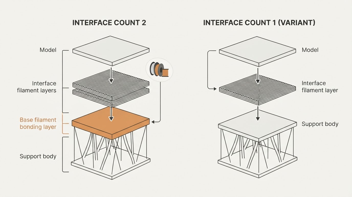
The interface is a dense band counted in printed layers, and the count includes the layer that faces the model. The material split comes from the Support Filament page as read on 28 October 2026, with the page last edited on 14 October 2026:
Interface layers | Interface filament | Base filament |
|---|---|---|
1 | 1 (the layer facing the model) | 0 |
2 | 1 | 1 |
3 | 2 | 1 |
N ≥ 2 | N − 1 | 1 |
At a count of 1 there is no base-material layer in the interface: the layer facing the model is the whole interface, and it uses the interface filament. From 2 upward you get exactly one bonding layer in the base filament. That layer is the last interface layer, at the back of the interface where it touches the support body and sits furthest from the model. It keeps the interface spacing and density so the interface material lands on a solid surface instead of on open support lines.
There is one documented exception. A soluble interface sitting directly on a non-soluble base with no Z gap is split differently: up to half the layers, and never more than two, print in the non-soluble filament so the soluble material has something rigid underneath.
Top and bottom interfaces are counted separately, each from its own value, so a bottom interface can keep the second material even when the top interface is turned off. The bonding layer counts as support base, so speed and cooling settings tuned for the interface do not apply to it. When Base is Default, the slice puts that layer in the current filament, normally the model material. That is the base-material layer you can see inside an interface you assigned to a different filament.
Documentation can describe a newer build than the one you have installed, so confirm the split in Preview rather than assuming your version matches the table exactly.
Set the profiles and assign them
- Add both filament profiles to the project's filament list: the model material and the interface material. Choosing a profile at slice time is separate from loading the spool, so you can configure the slice before the hardware is ready.
- Assign Interface to the second filament. Decide whether Base stays on
Defaultor gets its own filament number; if it stays onDefault, review Avoid interface filament for base. - Set Interface layers. Top interface layers and Bottom interface layers are separate values; with both set to 0 there is no interface at all, and support prints through with the base pattern.
- Check that the actual machine setup can feed and switch the filaments this slice uses. Automatic filament switching depends on the printer, its tool configuration and its firmware, so confirm that capability for the setup in front of you instead of assuming it from the slicer or from the number of nozzles.
- In the filament mapping for the job, map every filament number the slice uses to the extruder or slot that holds that spool.
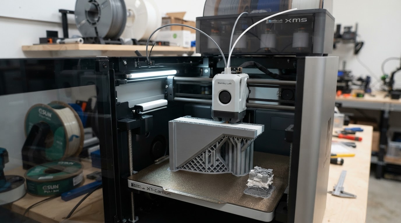
Setting Interface to a second filament introduces material transitions wherever the interface meets the rest of the support or the model. Setting the interface layer count to 1 puts the whole interface in the interface filament, but it does not remove every transition in the job: the model and the support body still use their own filaments, and an interface can appear on more than one layer band. Going from 1 to 2 interface layers also brings the base-material bonding layer into the interface, with its own tool change and purge on a multi-material printer. The slice's time and purge estimate shows what the change does to the job; judge it against the model you are printing.
Material flags and the pairing
Each filament profile carries two separate switches: Soluble material (filament_soluble) and Support material (filament_is_support). The Material Basic Information page describes both as materials commonly used to print supports and support interfaces. They are distinct flags rather than aliases, and neither one establishes that a given spool will release from a given model material.
The slicer does not pair materials for you, and a support-material flag is not a compatibility check. Use a pairing the material vendor supports for your model material, nozzle and machine, and follow that vendor's temperature and handling guidance. Support materials sold as breakaway, soluble or dedicated support grades are not interchangeable; the spool's documentation defines what it is meant to release from and which temperatures it needs.
Z distance is a separate setting from the filament assignment. Top Z distance and Bottom Z distance are rounded to a multiple of the layer height unless Independent support layer height is enabled, according to the Support Advanced page. That page also documents a Top Z distance of 0 as intended for soluble supports. Treat zero as a setting for a soluble interface rather than a universal gap for any two plastics; if a vendor has validated a non-soluble pairing, follow its gap instructions instead of assuming direct contact is safe.
Check the interface in Preview
Slice the model and inspect the support under the overhang before printing. Use the filament view and step through the layers at a top interface and, if the model has one, at a bottom interface. Confirm which filament the model, the interface and the support body each use at those layers, then check that:
- the interface filament is on the layer that faces the model;
- at an Interface layers count of 2 or more, the base-material layer is the last layer of that interface stack, furthest from the model, and at a count of 1 there is no such layer;
- top and bottom interfaces match their separate counts and their own positions;
- the filament numbers used in the slice match the extruder or slot mapping for the job;
- the time and purge estimate reflects the transitions the slice actually contains.
If the second material appears somewhere you did not expect, first work out whether you are looking at a top or bottom interface and where you are in that stack. The back layer of a multi-layer interface is base material by design, but a wrong count or a Base assignment you did not intend produces a different stack.
A correct Preview is a software check, not a successful physical test. After you confirm the assignment, print a small test with the actual spools if the pairing is new to you. Preview cannot show adhesion, release quality or whether the interface material survives the nozzle temperature the model material needs. If supports are still hard to remove once the interface is assigned, work through the general checks in this guide to supports that are too hard to remove before adding a second material to the job.