What the distance and layer count control
In OrcaSlicer, elephant foot compensation sits in the Advanced precision settings and is driven by two values. The Precision page in the OrcaSlicer wiki lists them under the variables elefant_foot_compensation, a float, and elefant_foot_compensation_layers, an integer. The missing h in "elefant" is the upstream spelling, so it is the name you will see in the profile and in command-line overrides rather than a typo you need to fix.
The two values do different jobs. Elephant foot compensation layers sets how many bottom layers are inset at all, and the distance sets how large that inset is on layer one. A positive distance shrinks the first layer by that amount, the offset then decreases linearly across the selected count, and every layer above that count is sliced to the model outline.
The same wiki page explains what the feature is for. The first few layers can print wider than the rest because of the weight of the material above them, thermal expansion, a bed temperature that is too high, or inaccurate bed height and levelling. The setting does not remove those causes. It trims the planned outline of the layers where the wider cross-section shows.
How the offset is calculated
For every layer numbered at or below the selected count, the documented equation is:
compensation = distance - (distance / layers) x (current layer - 1)
Layers are counted from one, so layer one gets the full distance and each later layer in the count loses one more slice of distance divided by layers. The layer count does not change the offset on layer one. It changes how long the correction lasts and how quickly it fades.
The formula also sets the limit that is easiest to get wrong. The last selected layer is not zero. With 0.25 mm over five layers, layer five still carries 0.05 mm, one fifth of the full distance, and layer six is the first layer with no offset. A count of one does end after the first layer, but every count above one finishes on a fraction of the distance instead of tapering away to nothing.
Worked example: 0.25 mm over five layers
Layer | Calculation | Path offset | Share of full distance |
|---|---|---|---|
1 | 0.25 - (0.25 / 5) x 0 | 0.25 mm | 100% |
2 | 0.25 - (0.25 / 5) x 1 | 0.20 mm | 80% |
3 | 0.25 - (0.25 / 5) x 2 | 0.15 mm | 60% |
4 | 0.25 - (0.25 / 5) x 3 | 0.10 mm | 40% |
5 | 0.25 - (0.25 / 5) x 4 | 0.05 mm | 20% |
6 and above | above the layer count | 0 mm | 0% |
The correction is not 0.25 mm on each of five layers. It is 0.25 mm on the first layer only, then a declining fraction of that distance on each of the next four, and it stops at 0.05 mm rather than reaching zero inside the count. These are offsets applied to the planned extrusion path, not five measured print errors, and 0.25 mm over five layers is a worked illustration rather than an OrcaSlicer default or a recommended starting preset.
Why this is not an all-height XY offset
An all-height XY offset works on a different geometric idea. The X-Y contour compensation setting changes the contour of every layer in the XY plane: positive values make contours bigger and negative values make them smaller. A negative contour offset therefore shrinks the part from the build plate to the top, including walls and features that were already at the intended size. Elephant foot compensation only touches the bottom layers named by its layer count, so the rest of the model keeps the outline you sliced.
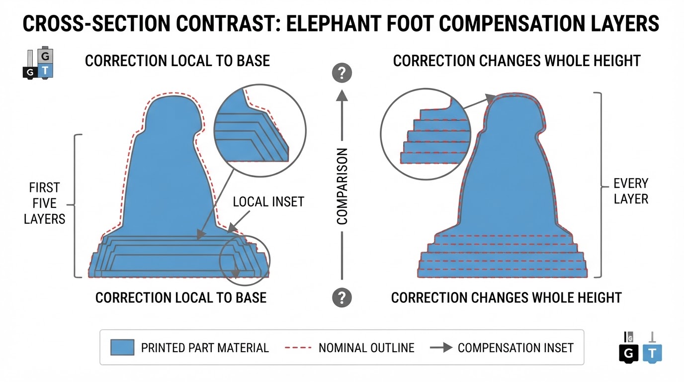
The sign conventions differ too, in a way that matters when you switch controls. A positive elephant foot compensation distance shrinks the first layer, while a positive contour compensation grows the contour. Carrying a positive value from one control to the other expecting the same result moves the part in the opposite direction. X-Y hole compensation is a third, separate control: positive values make holes bigger.
The taper addresses a bottom-layer outline. Consistently oversized outside dimensions at higher layers call for separate checks of the profile and printer; X-Y contour compensation changes outside contours, while X-Y hole compensation is for holes. The linked hole-compensation guide explains those separate signs and limits.
When the taper is skipped, and what it cannot tell you
The documented applicability limits are narrow. Compensation is applied when the object is printed directly on the build plate, and it is skipped when a raft is used. If your model sits on a raft, the value can be set and the outline will still not change.
A flare on the first layers is not proof of a slicer setting problem. The causes listed above call for different changes. Raising the compensation distance until the outline looks right in Preview does not tell you which cause you have, and it does not recalibrate first-layer height or the Z offset. The taper is a geometric correction to the outline, not a diagnosis of why the bottom of the part is wider.
There is also a cost to over-correcting. A large positive distance reduces the contact area of the footprint, which can weaken bed adhesion on parts that need it. With a high value, the preview can show the brim detached from the compensated footprint. The wiki treats that as a preview effect and points to the Brim use EFC outline option, which makes the brim follow the compensated outline. Its note assumes the printer is calibrated, so adhesion on the plate is something to confirm on a printed part rather than assume from the slice.
Elephant Foot Compensation Density is a separate control
OrcaSlicer also has an Expert-mode setting, Elephant Foot Compensation Density (elefant_foot_layers_density), which lowers the internal solid infill density on the compensated layers above the bottom layer to reduce excess material there. It does not change the outline offset and it does not replace the layer count; the distance and count work the same with the density left at its default.
A comparison that changes one setting at a time
A comparison is only readable if the model and the profile stay fixed and one value changes per slice: the distance or the count, not both.
- Start from a printed part rather than from the slicer. If you already have a cooled print with a wider base, measure or note the region that needs attention: how tall the wider zone is on that part, and where its outside wall steps back to the rest of the model. A zero-compensation Preview shows planned toolpaths, so it cannot reveal how far plastic spread on the plate.
- Save the project and record the current distance, layer count, layer height and first-layer settings. Keep the model directly on the build plate without a raft, so the feature can apply.
- Slice once with the distance at zero and the same profile. That slice is the planned baseline, showing the outline the model gets with no compensation, for comparison with the slices that follow.
- Change one value. Keep the count where it is and adjust the distance, or keep the distance and change the count. Slice and compare the same lower layers against the baseline rather than a different view or a different model.
- Read the planned geometry. Check which layers carry an offset, and confirm that the last compensated layer still holds distance divided by layers and that the next layer carries none. Preview can confirm the taper you asked for; it cannot confirm the size you will get.
- Print a small sample, let it cool, then measure the base and check that the brim and corners still hold.
There is no established conversion from a measured overshoot to the distance field. The value is a boundary offset applied to the path, while a caliper reading may be a full width or a diameter, so one measured error does not map one to one onto the setting. Adjust, slice and check instead of deriving the input from a single dimension.
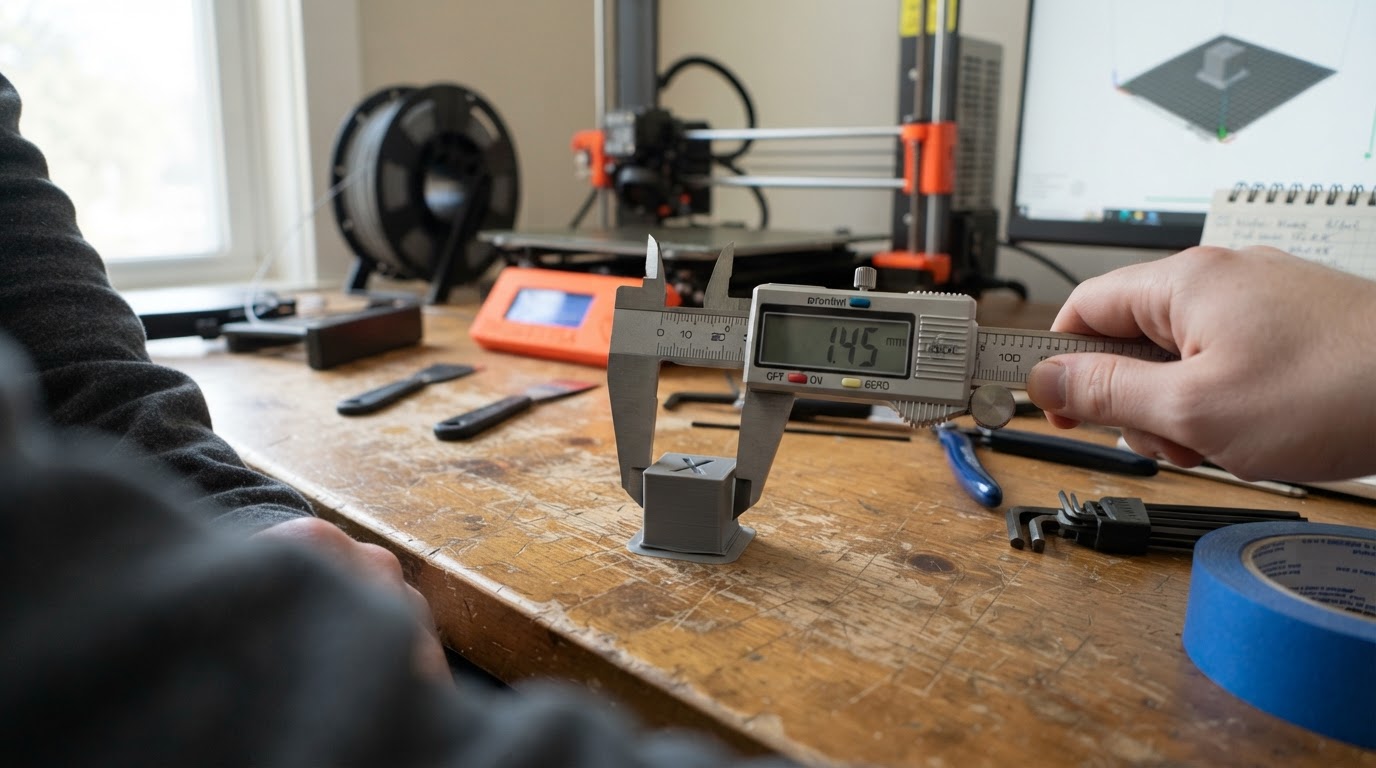
Compare the cooled sample with the fit and adhesion you need. If excessive inset reduced contact or detached the brim, reduce that excessive correction and verify again. If the base remains oversized, recheck the first-layer and bed conditions and adjust one appropriate setting at a time; a wide base is not, by itself, a reason to lower the compensation distance. Record the planned offsets and the actual result separately.