What the two signed settings change
Orca Slicer's current precision page lists X-Y hole compensation and X-Y contour compensation as Advanced settings. The direction is explicit: positive X-Y hole compensation makes holes bigger and negative makes them smaller. Positive X-Y contour compensation makes contours bigger and negative makes them smaller.
The two controls are not interchangeable. Hole compensation changes internal openings; contour compensation changes the outer boundary. If a hole and an outside wall are both off, record them as two observations rather than forcing one value to explain both.
A hole is surrounded by material. Moving its inner wall outward changes the local wall thickness, and a thin wall can print differently from a thick one. Do not promise that every unrelated outer dimension stays exactly the same after a hole change. That is why the measurement plan below records the outer or base dimension beside the hole.
Decide by symptom, then verify
Observation | First hypothesis | Reason |
|---|---|---|
Hole below the intended or mating size at mid-height | Positive X-Y hole compensation | Positive values enlarge holes |
Hole above the intended size | Negative X-Y hole compensation | Negative values shrink holes |
Outer wall below the intended size, hole close | Positive X-Y contour compensation | Positive values enlarge contours |
Outer wall above the intended size | Negative X-Y contour compensation | Negative values shrink contours |
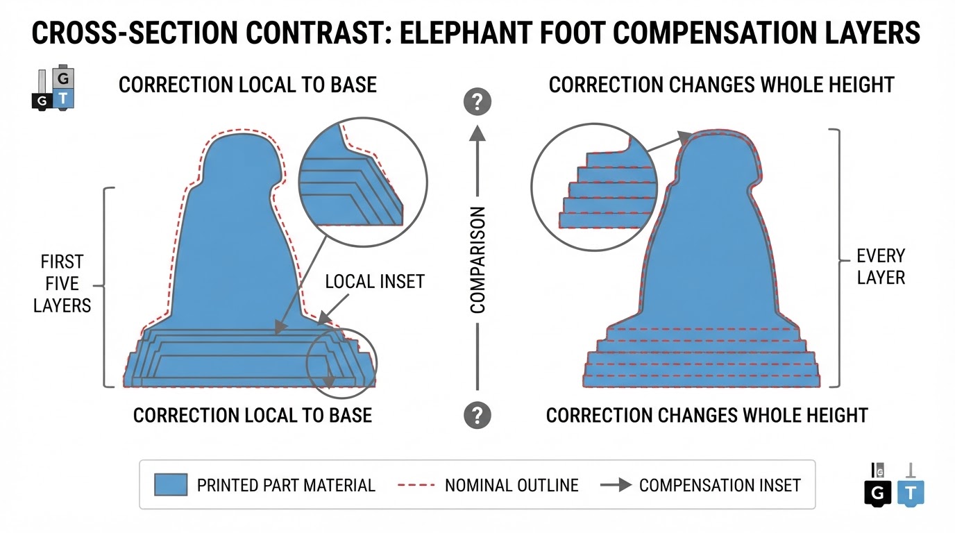
Tight only near the build plate | Check elephant foot separately | A first-layer effect is not an all-height hole error |
This table is a hypothesis, not a preset list. The correct sign still depends on what you measured and on the geometry around the hole.
Separate all-height from base-only
Measure the same hole near the base and again at mid-height. Undersizing at every height points toward a hole setting. A tight or flared bottom that clears higher up is a different problem: the current precision page describes elephant foot as a first-layer effect and notes that its compensation applies only when the object is printed directly on the plate and is skipped with a raft. Diagnose that separately instead of hoping a hole value fixes every height.
Use the official tolerance model
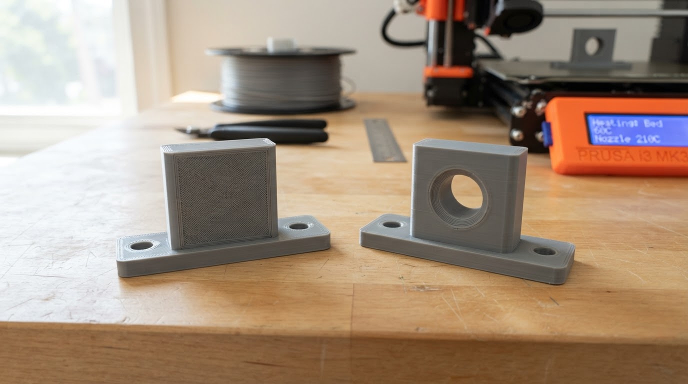
The official tolerance calibration page gives a fit test you can reproduce. In Prepare mode, right-click the plate, choose Add Handy Model > OrcaToleranceTest. The coupon has six hex openings at nominal offsets of 0, 0.05, 0.1, 0.2, 0.3 and 0.4 mm, plus a hexagon tester. Use a suitable 6 mm Allen key or the printed tester, measure both the holes and the inner tester with calipers, then fine-tune X-Y hole and contour compensation and repeat the process.
A fit coupon's clearance is not printer accuracy or calibrated metrology. The intended hole and the actual key or tester dimension may differ, and calipers have resolution and jaw-contact limits. Record what you measured, not just whether the key felt loose.
Run a controlled trial
Work from the exact Orca Slicer version and UI you have open, change one compensation field at a time, and keep the material, nozzle, profile and coupon identical between prints. Do not assume a universal radius or diameter formula: a measured diameter error is not automatically the number to enter, because the slicer applies its own offset and the surrounding geometry also matters. Print, measure the hole, the outer or base dimension and the mating part, then decide the next single change.
One trial is not repeatability or causality. Print comparable coupons, measure the same features the same way, and only conclude after the direction repeats. A single clean fit can be luck; a repeated direction is evidence about your setup.
Blank repeat-trial log
Copy this table before the first print. Leave the observed columns empty until you measure; write the expected direction in Notes only as a hypothesis.
Slicer / version | Material / nozzle / profile | CAD hole / outer dimension | Compensation setting (hole / contour) | Measured hole | Measured outer / base | Mating-part measurement | Notes |
|---|---|---|---|---|---|---|---|
|
|
|
|
|
|
|
|
|
|
|
|
|
|
|
|
|
|
|
|
|
|
|
|
Keep the same calipers, measuring points and coupon orientation for every row.
Where this fits in calibration
Tolerance is the last step, not the first. Our calibration guide sets out the official order and explains why tolerance comes after the filament tests. The calibration-order article covers the filament sequence, the optional advanced checks and the record worth keeping. Run those first if temperature, flow or pressure advance is still changing.
The useful result is a direction you can measure again, not one perfect coupon.