What the Setting Changes
In Orca Slicer, infill wall overlap is infill_wall_overlap, an Advanced-mode percentage setting in the Strength section, documented on the Strength settings page. The page's CLI example is --infill-wall-overlap=20%; that line shows the syntax, not a recommended value.
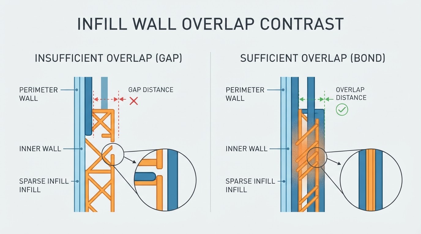
Its job is narrow: the infill area is enlarged slightly so it overlaps the wall. It does not move the wall, change the wall count, or alter the sparse infill pattern. What changes is where the planned infill region ends relative to the wall.
At a low or zero value, the nominal infill paths can still meet the wall's nominal boundary, because the setting controls how far the region is enlarged, not whether the paths exist. A low number is therefore not by itself evidence that plastic stopped short of the wall. At a higher value the planned junction moves further into the wall boundary. Whether the two extrusions bond in the printed part depends on extrusion and flow, cooling, geometry and the rest of the profile, which one percentage does not settle.
What the Percentage Is Measured Against
The wiki describes the value as approximately relative to the inner wall line width. It then gives the precise definition: half the inner wall line spacing plus half the internal solid infill line spacing with the Classic wall generator, and the inner wall line spacing with Arachne, with the outer wall line spacing used in both cases where only one wall is printed.
Two consequences follow.
First, 12% is not 12% of a fixed 0.4 mm. It is a fraction of a spacing that changes when you change wall line width, sparse infill line width, or wall generator, so the same number can produce a different absolute depth on two profiles.
Second, a Classic profile and an Arachne profile cannot be compared by percentage alone. The distance the infill travels into the wall is calculated from different spacings, so a value that looks right on one generator does not carry over unchanged.
Older wording that described the percentage as a share of sparse infill width does not match the current page. The saved documentation was checked on 2026-10-24, and installed builds can differ from it.
Why the Documentation Suggests About 10-15%
The wiki suggests setting this value to about 10-15% to minimize potential over-extrusion and accumulation of material that produces rough surfaces. Read that as a band for limiting excess material at the junction, not as a tested optimum. The page describes the purpose of the range; it does not report a measured strength gain for a particular value.
The reasoning behind keeping it low is about volume. More overlap moves the planned infill further into a space the wall already occupies, and the wiki attributes the rough surfaces to over-extrusion and accumulated material. A lower value moves the planned junction back; that does not guarantee a cleaner wall, and a higher value does not guarantee a bonded joint. Both outcomes still depend on how the profile extrudes.
Three Controls That Sound Similar
Several settings carry "wall overlap" in their names and act on different surfaces.
Control | Variable | Surface it changes |
|---|---|---|
Infill Wall Overlap |
| The sparse infill region where it meets the inner wall |
Top/Bottom Infill Wall Overlap |
| The solid top and bottom skins where they meet the walls |
Precise Wall |
| The spacing between the outer and inner walls in Inner/Outer order |
The sparse infill wall overlap value is set on its own. Top/Bottom Infill Wall Overlap is the separate solid-skin control of the same family: the wiki says the top solid infill area is slightly enlarged to overlap with walls for better bonding and to minimize pinholes where the infill meets the wall. It is a different variable, set on a different page, and if pinholes appear only on top surfaces this is the control that applies.
For the related spacing control, see our Precise Wall guide. Precise Wall belongs to the precision settings. The precision documentation describes it as slightly increasing the spacing between the outer wall and the inner wall when printing in Inner/Outer order, to improve dimensional accuracy. It changes a pair of wall paths; it does not set how far sparse infill reaches into the wall.
What Preview Can and Cannot Show
Preview draws the planned toolpaths. For this setting it can show where the slicer intends the infill path to end and whether sparse infill reaches or extends into the wall region, down to the resolution the display can render. That is enough to compare two slices of the same model.
It does not show deposited plastic. Planned paths are not ridges, gaps, bonding or strength, so Preview cannot tell you whether the junction will be over-extruded, whether the wall surface will come out smooth, or how strong the part will be. Those questions need a printed comparison, which is why a plan-level check and a physical check answer different things.
The same limit applies to reading a printed part. An infill wall gap in OrcaSlicer, or a rough patch near the junction, is not specific evidence that this value is wrong: flow ratio, extrusion width, temperature, cooling and part geometry can leave similar marks. Changing the overlap is a way to see what the setting does to the planned junction, not proof of the cause of a physical defect.
A Comparison Procedure That Holds Up
Keep the rest of the profile identical so the overlap value is the only difference: the same model, filament, nozzle temperature, flow ratio, line widths, wall generator and wall order. Duplicate the profile first, so the original stays available for the next comparison.
- Choose a model with a flat outer wall and enough interior volume for sparse infill to meet that wall.
- Record the current
infill_wall_overlapvalue, the wall generator, the wall and sparse infill line widths, and the profile name. - Change only the overlap value.
- Slice both versions and inspect the same layer height in Preview, comparing where the planned infill path ends relative to the inner wall.
- If physical performance matters for the part, print both samples from the same spool and profile and compare the junction on each. Measure the outer wall the way you measure dimensions.
- Add the result to the same record: what Preview showed, what the print showed, and anything that changed between the two slices.
A few profile choices change what the number tells you. Because the denominator depends on wall spacing, a variable-width Arachne profile can produce a different absolute depth than a Classic profile at the same percentage, so compare the two planned junctions instead of translating the number between generators. A single-wall model follows the same rule: the denominator switches to the outer wall spacing, so the same percentage is a different distance.
Small features need the same care rather than a separate method. The overlap distance scales with the spacing, so on a tiny feature the added material can be a large share of the local space; inspect the layers that actually carry that feature.
Infill-first printing changes the junction from the other direction. The wall and surfaces documentation warns that when infill and shells print before the walls, the infill pushes slightly out on the printed walls where it attaches, worsening the external finish, and recommends Precise Wall, an Inner/Outer/Inner wall order, or reducing Infill/Wall Overlap in that situation. Keep infill-first and wall order fixed for an overlap comparison; test a different interaction in a separate comparison.
The record from step 6 is what makes the next round faster: it shows whether the geometry, the line widths, the wall order or the overlap value changed between two prints whose junctions look different.