What the setting changes, and where it lives
Avoid crossing walls (reduce_crossing_wall) sits with the wall and surface options in the Quality category, among the advanced controls, which remain visible in the Expert view as well as in Advanced. Its scope is narrow: it changes the routing of travel moves, the non-extruding moves between one extrusion and the next. It does not move the wall, alter the extrusion path, or add material.
The official OrcaSlicer wall and surface settings reference describes the trade-off: detouring can significantly reduce surface defects and stringing, especially with materials such as PETG or TPU, at a slight increase in print time, and it recommends the option for detailed or aesthetic prints. The CLI equivalent for a profile override is --reduce-crossing-wall=1.
Max detour length caps the extra distance
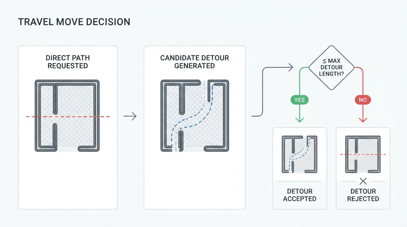
The companion field, Max detour length (max_travel_detour_distance), does not limit the total length of the routed path. The current implementation subtracts the direct travel length from the routed length and compares that difference with the limit: detour = routed length − direct length. A millimeter value sets the cap directly; a percentage is calculated from the direct travel length. The check in the avoid-crossing routing code discards the detour only when the extra distance is greater than the limit.
Take a hypothetical move with a 40mm direct line and a 60mm route around the wall. The route adds 20mm. A 25mm cap allows it, a 50% cap on that move also allows it because 50% of 40mm is 20mm, and a 10mm cap rejects it, so the travel falls back to the straight 40mm line. These lengths are illustrative, and the exact behavior depends on the source and build you are running.
Max detour length | Extra distance allowed on a 40mm direct move | Result for a 60mm route |
|---|---|---|
| Up to 25mm extra | Taken: adds 20mm |
| Up to 20mm extra | Taken: adds 20mm |
| Up to 10mm extra | Rejected: direct line used |
| No length limit | Taken if the planner finds it |
A percentage moves with the length of the travel. On a 100mm direct move, 50% permits 50mm of extra path, not a 50mm total route. 0 removes the length check, not the feature itself: detours of any length become permissible, but the rest of the routing logic still applies, so a route still has to be found.
Why a crossing can still appear
When the available detour needs more extra distance than the cap allows, OrcaSlicer restores the original straight travel, and that line crosses the wall. Reading the result as "the setting did nothing" misses the interaction: the feature offered a route, and the limit refused it.
The cap is not the only reason a crossing can remain, though. The planner may not be able to build a usable route around the local geometry, and the preset or build that produced the file may not contain the values you expect. Look at the travel in Preview for the active preset before deciding which of those cases you are in.
It also helps to separate this from stringing as a whole. Avoiding crossings can reduce the marks a nozzle leaves when it drags across a wall, but the reference describes it as reducing defects and stringing rather than eliminating crossings entirely, and it does not cover stringing caused by temperature, moisture, or the material itself.
Check the slice instead of trusting the checkbox
A ticked box records a preference; it does not show that the toolpath changed. Check the slice:
- Confirm which preset produced the file. Select the printer, nozzle, filament, and process preset actually used, then slice again; an edit in an unselected profile changes nothing.
- Confirm the value and its unit. A
50in the field that is read as a percentage and a50read as millimeters are different caps. - Slice, then open Preview and display travel moves on the layer you care about.
- Read travel separate from extrusion. Extrusion lines are the printed walls and infill; travel lines are the non-extruding moves between them. A line that merely runs beside a wall is not a crossing.
- For each remaining crossing, compare the extra distance of the route you expected with the cap. If the extra distance is over the cap, the fallback to the direct line is the expected result.
When to change the number, and when to change the approach
Raise the cap when the remaining crossings are the ones causing visible marks and the added travel time is acceptable for that job. Setting it to 0 for one test slice is a quick way to learn whether a longer detour exists at all; keep the result only if the time cost is worth it.
When you want to reduce travel overall, fewer and shorter non-extruding moves leave fewer chances for a crossing, but that is a decision about ordering and geometry rather than about this one field.
If the problem is a dragging nozzle rather than a wall crossing, the relevant control is vertical clearance, not routing. Z-hop raises the nozzle during a retracting travel move and lowers it before extrusion resumes; it does not choose a path around a wall. This OrcaSlicer Z-hop guide covers that separate task, including why a configured hop can still fail to appear in a slice.
Where the geometry offers no shorter route, a larger number cannot manufacture one. In that situation, the honest options are to accept the crossing, change the part orientation or wall layout, or treat the surface marking as a post-processing problem. The setting is a routing preference with a measurable cost, not a switch that removes every wall from the nozzle's path.