Why painted supports seem to disappear after a re-slice
Support painting is the OrcaSlicer tool that lets you add or remove support structures by painting directly on the model. The official Support Painting wiki page describes its purpose in one line: it is for models with overhangs or complex geometry where you want to control where supports are placed, for better print quality and easier removal. Painting is an instruction to the support generator, not a promise that support geometry will be built wherever you painted.
Three conditions decide whether a painted instruction becomes visible support geometry:
- Supports are enabled for the object you painted, not only for the plate.
- The correct object or part is selected, because painting is stored per object.
- The plate has been re-sliced after the last paint stroke, so you are reading the new result.
When one of those is wrong, the paint looks ignored even though it was recorded.
What painting controls, and what it does not
It paints a direction, not a structure. The documented behaviour is add or remove: one mode tells the generator to place support where it would not have placed it, and the other tells it to leave the painted area alone. Names and toolbar placement are version-sensitive, so confirm your mode from what it describes rather than from an older tutorial.
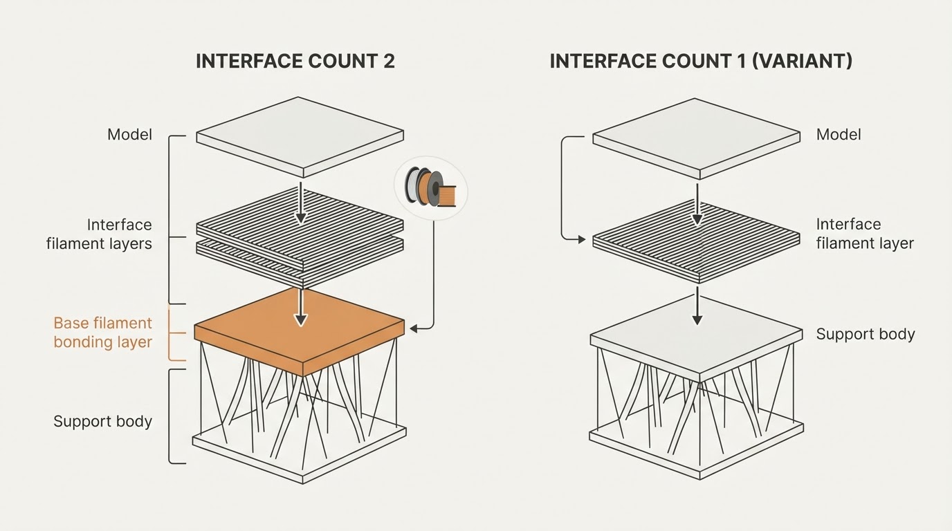
Contact surfaces and support trunks are two different things. Conservative suggestion: a painted patch on the underside of an overhang marks an area where support is allowed to touch the model. It does not create the trunk that carries that contact down to the build plate. If the surrounding geometry leaves no printable path to a base, the slice can come back with little or no support under your paint. Treat painting as the top of a chain - contact, interface, trunk, foundation - not as the whole chain.
Painted blocking and support geometry are different. Painted blocking marks model surfaces; it is not the same operation as cutting a solid volume out of generated support. Inspect where a remaining branch contacts the model before deciding that the paint was ignored. Do not assume a painted surface or blocker volume will remove every crossing tree branch in every version.
Scope decides whose settings win. Conservative suggestion: painting applies to the object you selected, and that object's own support settings, a build-plate-only restriction, or a scope option that limits support placement can change the result before your paint is considered. If painted areas behave inconsistently across objects on one plate, inspect each object's own settings before repainting.
The tool has a documented default shortcut. On the official keyboard shortcuts page, the default key for the paint-on supports gizmo is L, and while a painting gizmo is open the documented defaults are C circle, S sphere, F fill, G gap fill, T triangle, and H height range. Ctrl plus the mouse wheel changes the pen radius, and Alt plus the wheel moves the section. Those keys are defaults and most can be reassigned, so verify them in your build.
How to add manual supports without fighting the automatic pass
Keep the test model small - a single small overhang is enough - because the value here is the loop, not the print.
The official support settings reference lists normal(auto), tree(auto), normal(manual) and tree(manual). Auto modes choose support from geometry as well as manual placement; manual modes limit generation to manually specified areas. For this paint-only exercise, select a manual type. Capitalization and menu layout can differ by release.
- Select the object and the part you want to paint. Painting follows the selection, so the wrong part is the first way for a stroke to end up somewhere you never see.
- Enable supports and choose the support type. For a paint-only test, use
normal(manual)ortree(manual)in the Support settings. Check the effective object settings, not just a global preset. - Open the paint-on supports gizmo. The documented default is
Lin the Prepare view. - Pick the direction you need and set the brush. Choose the add or remove mode that matches your intent, size the brush for the surface, and use
Ctrlplus the wheel to adjust the radius as you go. - Paint only what you need. Keep the stroke inside the surface you mean, rotate the model, and check the true underside instead of trusting the angle you started from.
- Inspect scope and conflicting settings. Check the object's own support settings, any build-plate-only restriction, and any scope option that limits where support may be placed; a conflicting setting can beat a correct paint.
- Re-slice, then inspect the preview. Step through the layers, look at the support contact points under the painted area, and confirm that each contact has a printable path down to a base.
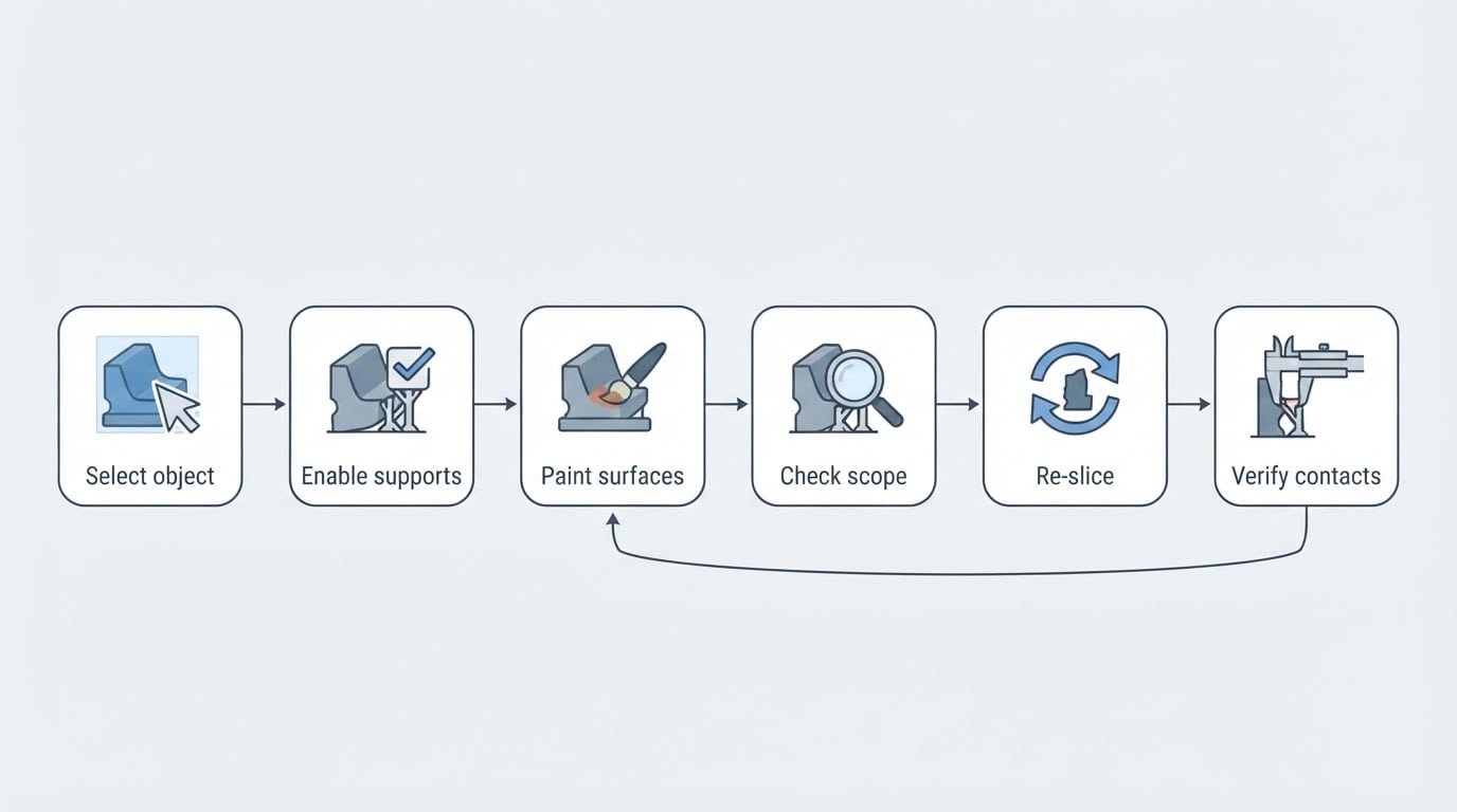
Workflow illustration, not a software screenshot. Select a manual support type for the paint-only procedure described above.
Completion standard: support appears where you asked for it, none appears where you blocked it as far as the geometry allows, and every contact point has a path to the plate. If not, change one thing - paint, scope, or a support setting - and run the loop again.
Symptom, check, next step
Symptom | What to check | Next step |
|---|---|---|
Painted area slices with no support | Supports enabled for that object? The right object or part selected? Re-sliced after painting? | Enable supports for the object, reselect it, re-slice, then inspect the layers under the paint. |
Support appears under only part of the painted area | Is the intended contact visible and is there a feasible support path? Are placement restrictions active? | Compare a small test overhang, inspect restrictions one at a time and re-slice; do not print an unsupported result. |
A painted blocker leaves support behind | Does the remaining structure contact an unblocked surface, or is it a branch connecting another contact? | Inspect the contact layer, check the selected object and re-slice after one change. |
Support shows up outside the painted area | Is the type still Auto? Are you looking at a trunk rather than a contact surface? | Use a manual type for the paint-only test and compare support contact points in Preview. |
Pre-print checklist
- The painted object is selected, printable, and has supports enabled.
- A manual support type is selected for a paint-only test.
- The paint sits on the object or part you meant, and the underside was checked from more than one angle.
- Object-level support settings, build-plate-only restrictions, and scope limits were inspected.
- The plate was re-sliced after the last paint stroke.
- Layers and support contact points were reviewed, and every contact has a path down to a base.
FAQ
Why does my Orca Slicer support blocker not work?
Several different problems can look like this: viewing an old slice, painting the wrong object, retaining automatic generation, or confusing a branch with its contact point. Check those separately. A small test model can reveal whether the setting is being applied before you change the full project's support layout.
How do I add manual supports in Orca Slicer without covering the whole model?
Enable supports, select a manual type, open support painting and mark the surfaces that need support. Keep strokes tight and size the brush down for detail. Re-slice and inspect the contact points, including any other overhangs you left unpainted.
Do I need to switch to a manual support mode first?
For the paint-only workflow in this article, yes: use a manual support type. Painting can also supplement automatic support generation, but that is a different baseline. Always check the resulting slice before printing.
If placement is correct but supports bond too firmly, use our separate guide to OrcaSlicer supports that are too hard to remove. For motion and flow limits, see OrcaSlicer speed settings; those settings do not replace correct support placement.