What Z offset really controls
Z offset is the distance the nozzle holds above the build plate when the printer believes Z is at zero. Every first-layer decision follows from that single number: how firmly the plastic presses into the plate, how wide each extrusion spreads, and how well one line bonds to the next. Too little gap and the nozzle drags through molten plastic; too much and the lines sit on the plate as separate strands instead of a bonded sheet.
The first layer is the most honest test of that gap. Later layers can hide a bad offset — a print may still finish while the corners lift, the underside looks ragged, and the part fails the moment bed adhesion is tested. Calibrating against a controlled first-layer patch takes a few minutes and removes an entire class of problems before flow, pressure advance, or print speed ever enter the picture.
Inputs and prerequisites
Z offset calibration cannot succeed if the rest of the first layer is unstable, so set these up first:
- A clean plate. Oils from fingerprints are the most common reason a correctly calibrated offset still fails. Wash the sheet with warm water and a mild dish soap, dry it, and handle it by the edges.
- The right plate definition selected. Smooth and textured sheets behave differently: the published guidance for Orca Slicer's first-layer stack notes that smooth PEI wants more squish while textured PEI wants less, which is why plate-specific presets exist.
- A dry filament and a known first-layer temperature. Wet filament foams, and the surface behaves unpredictably no matter where the offset sits.
- A trammed bed and a fresh mesh. If the plate is tilted or the mesh is stale, the offset will be right in one area and wrong in another.
- A small single-layer patch. A simple square or rectangle, roughly the footprint of a test card, is enough to read the result. You do not need a full part to judge a first layer.
- A way to adjust while printing. Orca Slicer supports live Z-offset adjustment, which lets you change the value during the test patch instead of restarting between attempts.
Where Z offset is adjusted on common setups
Most setups expose Z offset in more than one place, and knowing which one you are changing prevents double compensation:
- The printer itself. Many machines store a Z offset in firmware, set through the printer's own control screen. The printer owns that value, and it can be lost or reset with a firmware update or a factory reset.
- The slicer machine profile. With live Z-offset adjustment in Orca Slicer, the number you dial in can live with the machine or plate profile. Profile-side values travel with the profile, so the same setup behaves predictably when you move a print between machines.
- Machine start G-code. Orca Slicer leaves bed-probing routines such as
G29and Klipper bed mesh handling to machine start G-code, which keeps profiles portable and keeps the mesh routine tied to the printer rather than to the model.
The caveat is stacking. If the firmware already applies an offset and you add another one in the slicer, the two combine and the nozzle ends up closer than either value suggests. Start from a known-neutral firmware value, tune with one authority, and only add the second as a saved, documented adjustment for a specific plate or filament.
Run a first-layer test and dial it in
With the prerequisites in place, the calibration loop is short:
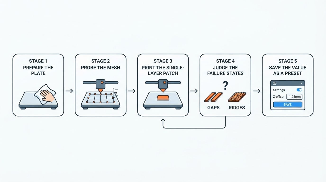
- Heat to real printing conditions. Bring the bed to its target temperature and the nozzle to the first-layer temperature for the filament. Judging the first layer while the bed is still warming is a common source of noise.
- Print the single-layer patch. Watch the first lines as they go down and adjust the offset in small, repeatable steps. Change one increment at a time, and give the extruder a few lines to settle before judging.
- Deliberately find both bad states. Move the offset until the lines are clearly too far apart, then move it the other way until the surface is clearly too squished. The usable value sits between those two failures, not at the first setting that looks acceptable.
- Settle in the middle. Once both extremes are known, choose the value where the lines just merge, the surface is flat, and the nozzle leaves no drag mark.
- Reprint to confirm. Run the patch again from the saved value without touching the offset. A calibration that only works while you are actively adjusting it is not finished.
- Record and save. Store the value with the plate or machine profile as a preset, and note the plate type, filament, and temperature it was tuned for.
Repeat the loop once per plate type, then once per material family if your profiles are not already separated. Taking notes at step 6 is what turns a calibration into a repeatable setup instead of an afternoon of re-tuning.
What a good first layer looks like
Judge the finished patch on structure, not on a feeling:
- The individual lines just visibly merge, with no gaps left between perimeters and infill.
- The surface is flat and matte, with a slight uniform texture and no shiny ridges where the nozzle plowed through.
- Extrusion width looks consistent across the patch, including corners and the first few lines.
- Once cooled, the patch comes up as a single flexible sheet rather than splitting into separate strands.
Two failure states tell you which way to move:
- Too far: round-topped lines, visible gaps, weak adhesion, and strands that separate when the patch is flexed.
- Too close: a glossy, rippled, or translucent sheet, visible drag marks, and over-extrusion ridges that push plastic sideways.
Read together, the two failures give you the direction: too far leaves round-topped lines with gaps; too close flattens the lines into a shiny, ridged sheet.
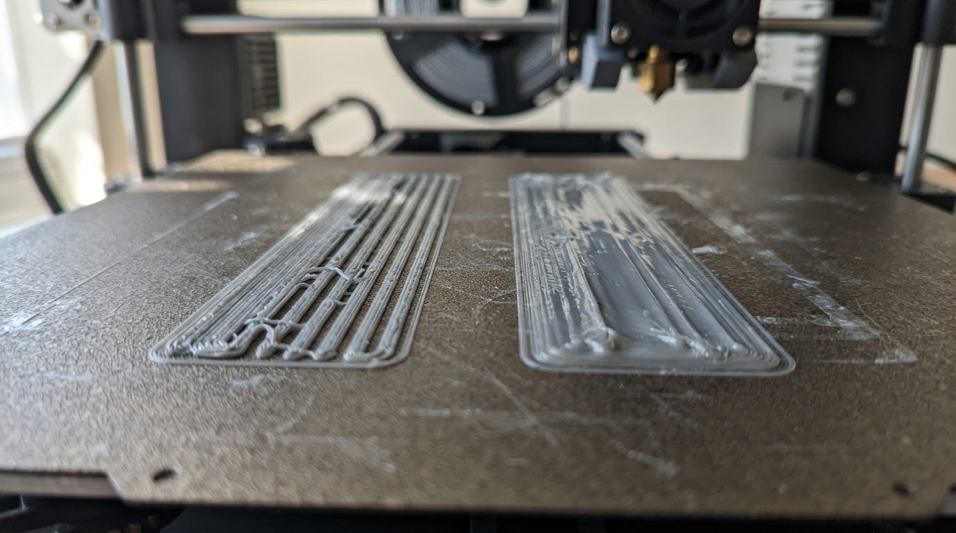
For the surrounding settings, the published first-layer recipe on this site is a useful starting point: first-layer speed no higher than 20 mm/s, a nozzle temperature roughly 5-10 °C above the normal printing value, and a bed about 5 °C warmer, with a PLA example of 215 °C and 60 °C. Treat those as a documented recipe to verify on your own machine, not as universal defaults.
Common mistakes that throw off the result
- Correcting in large jumps. Big changes overshoot in both directions and make the usable window hard to find.
- Testing on a contaminated plate. Grease, dust, and glue residue change adhesion more than a small offset change does.
- Ignoring the plate type. The same offset that suits a smooth PEI sheet can be too much for a textured one.
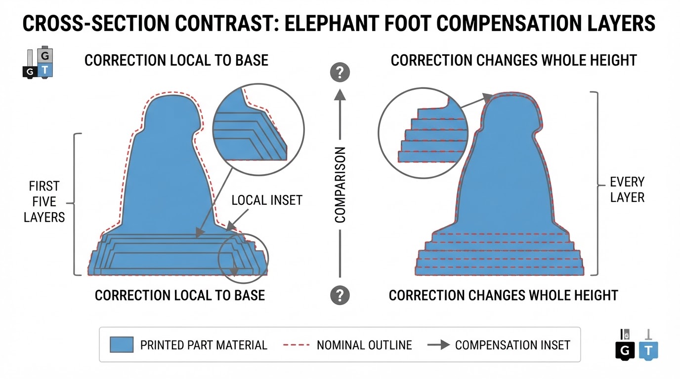
- Using Z offset to fix elephant's foot. That is a different correction. The published recipe for this site's first-layer stack uses a negative First Layer Expansion of about -0.2 to -0.3 mm with first-layer flow around 95-98% to pull the flare back in.
- Chasing a tilted bed with offset. If one corner is high and another low, tram the bed and rebuild the mesh instead of splitting the difference with Z offset.
- Leaving two offsets active. A firmware value plus a slicer value stack, and neither one alone describes the real gap.
- Changing several variables at once. One change, one patch, one observation.
- Judging a hot patch. Let the test cool; warm plastic hides gaps and weak bonding.
Make the result stick
Once the offset is right, the surrounding Orca Slicer first-layer tools keep it right. Plate-specific presets let you save a value per sheet, so swapping from a textured plate to a smooth one does not restart the calibration. Adaptive Bed Mesh handles unevenness across a plate, while Mouse Ear Brims add local hold-down material where small parts are most likely to lift — for example, a 4-6 line brim on the corners of a small print. Because bed-probing routines such as G29 and Klipper mesh handling stay in machine start G-code, the same profile can move between printers without dragging the wrong mesh logic along.
For a multi-brand fleet or a small print shop, the practical rule is one documented offset per plate and material combination, saved as a preset and updated only after a repeatable test. That is the difference between a calibration you did once and a first layer you can trust every morning. The first-layer and bed-adhesion guide on this site collects the same recipe and presets in one place.
When Z offset is not the problem
Calibration has limits, and recognizing them saves time:
- A warped or damaged plate cannot be corrected by offset; it needs a replacement or a mesh that accounts for it.
- A partially clogged or worn nozzle changes extrusion width independently of the gap.
- Wet filament, a miscalibrated extruder, or loose mechanical components all mimic first-layer problems.
- If the mesh is not loaded, or start G-code overrides it, the offset will be tuned against the wrong surface.
Calibrate the offset after those items are stable, not before. A first layer that is correct, repeatable, and saved is the foundation every later calibration step assumes.