What Infill Combination Actually Changes
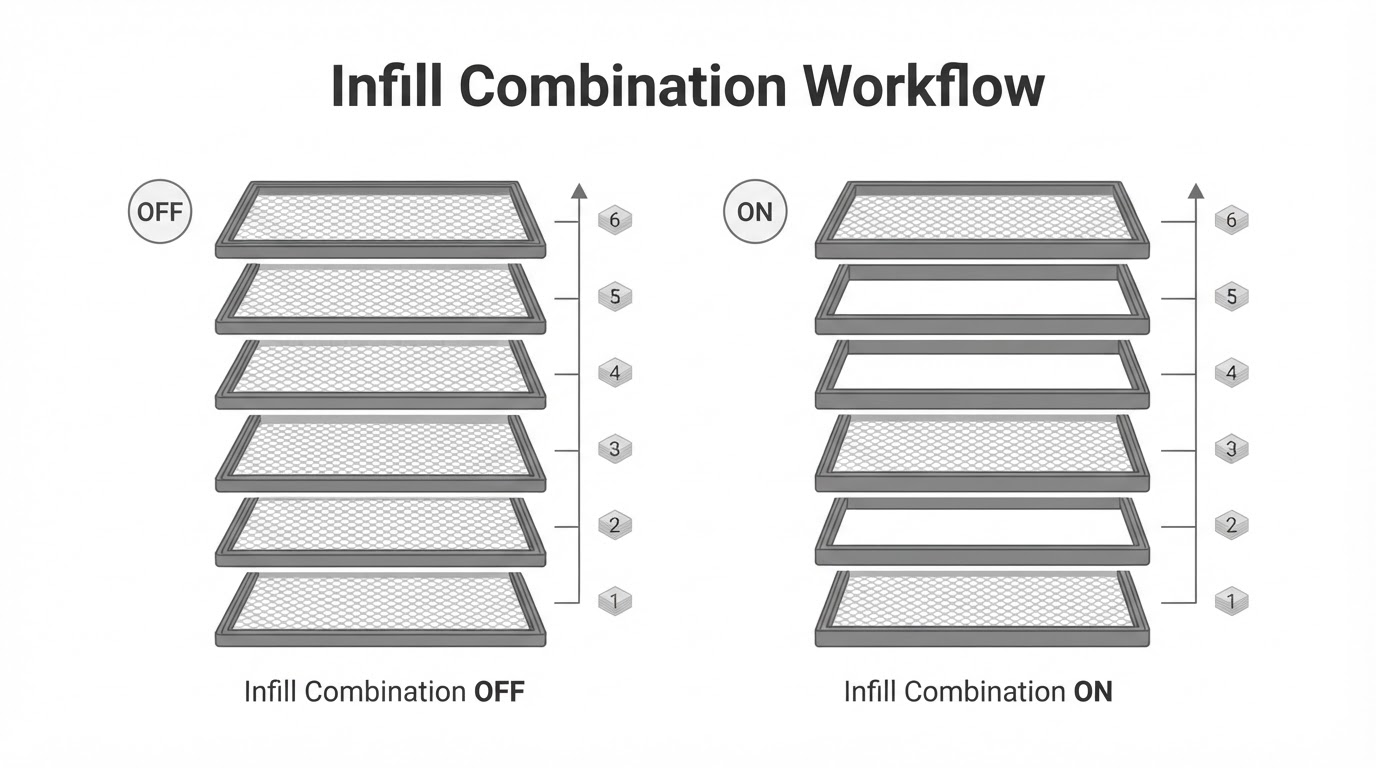
Orca Slicer's Infill Combination is a sparse-infill control. When it is enabled, the slicer can print the sparse infill for more than one layer in a single combined pass, while the walls still print at the layer height set by the process profile. The upstream Strength Advanced wiki describes it as combining sparse infill from several layers so that the infill prints together, while the walls keep their original layer height.
The important word is sparse. The wiki's description is limited to sparse infill; it does not describe a change to the requested infill density, the chosen pattern, or the solid top and bottom shells. In practical terms, the setting changes how many sparse layers share a toolpath. If you are still deciding which pattern to use, that is a separate decision, and the infill-pattern guide covers pattern structure and how to verify a slice. This article stays on the combination setting.
It is also separate from variable layer height. The wall layer height is not being varied here; the walls keep their normal layer height, and only the sparse infill is scheduled across a taller combined height.
Where the Setting Lives
In Orca Slicer, open the process settings for the profile you are printing, select the Strength tab, and look in the Advanced group. The control is labelled Infill Combination. It is a boolean: on or off. The field beside it sets the maximum layer height for the combined sparse infill; you will also see it described as the max combined height. Read the label in your own build before changing it, because controls can be renamed or regrouped between releases.
The value accepts millimetres or a percentage of nozzle diameter, and the two forms stay distinct: a bare 0 is a millimetre value, while 100% is a percentage of the nozzle diameter. The upstream wiki gives two anchors:
- Numeric 0 or 100% uses the nozzle diameter, which it describes as the option for the maximum reduction in print time.
- A value around 80% is the wiki's suggestion for maximising sparse-infill strength.
That 80% figure is a suggestion from the documentation, not a proven optimum for your part. The same page adds a hard limit: the value must not be larger than the nozzle diameter. A 0.4 mm nozzle therefore caps the documented range at 0.4 mm, or 100%.
How the Max Height Becomes a Layer Count
You do not type a number of layers. You type a height, and the slicer derives the count by dividing that height by the layer height and rounding down to a whole number. That rounding is the usual reason two profiles with the same max height behave differently.
Two worked examples
Take a hypothetical 0.4 mm nozzle, a 0.16 mm layer height, and a 0.32 mm max combined height. Divide 0.32 by 0.16: the result is 2, so the maximum is two sparse layers combined. That is an arithmetic ceiling, not a promise that every region of the model will combine. With the same 0.32 mm max and 0.20 mm layers, 0.32 divided by 0.20 is 1.6, which rounds down to 1. The setting is still enabled, but there is no second layer to merge, so the print can look unchanged.
The same arithmetic explains why people describe this as "Orca slicer infill every other layer": at 0.16 mm layers and a 0.32 mm max, the theoretical result is infill on every second layer. At a 0.4 mm max and 0.16 mm layers, the result is still two layers, because 2.5 rounds down to 2. At 0.20 mm layers, 0.4 divided by 0.2 is 2, so two layers fit again.
Arithmetic reference table
Max combined height | 0.16 mm layers | 0.20 mm layers | What the arithmetic allows |
|---|---|---|---|
0.24 mm | 1 | 1 | No two-layer merge |
0.32 mm | 2 | 1 | Up to two layers at 0.16 mm; none at 0.20 mm |
0.36 mm | 2 | 1 | Up to two layers at 0.16 mm; none at 0.20 mm |
0.40 mm (numeric 0 or 100% uses the 0.4 mm nozzle diameter) | 2 | 2 | Up to two layers at either layer height |
This table is illustrative floor arithmetic only, not a guarantee that eligible regions combine. The slicer still decides which regions are eligible, and these numbers are not measurements from a printed part.
Why the Merge May Not Appear
When the preview looks the same after you enable the setting, work through the possibilities in order rather than changing several controls at once.
Start with the count
If the max height divided by the layer height rounds down to 1, there is no second sparse layer to combine. That is what happens with 0.32 mm max and 0.20 mm layers. A larger max height can change the arithmetic, but it still has to stay within the nozzle-diameter limit documented by the wiki. A thinner layer height can also move the result above 1, because the divisor changes.
Then check the region
The setting has nothing to combine in a layer that contains no eligible sparse infill. Walls, solid top and bottom shells, and small areas that the profile treats as internal solid infill are not sparse regions. In Preview, check whether the layer you are examining actually contains a sparse region; if it is mostly wall or solid shell, the setting has nothing to combine there.
Check the build you are running
The upstream wiki documents current upstream behaviour. Your installed build may be older, or it may be a different build with another label or default. Match the control by what it does, and do not assume that a screenshot or label from another release describes your copy.
What you see | First check | Next action |
|---|---|---|
No change in sparse layers | Max height divided by layer height | If the result rounds to 1, raise the max height within the nozzle limit or use a thinner layer height |
Only some sparse layers combine | Whether those layers contain eligible sparse infill | Inspect the region for walls, solid shells, or replaced small areas |
The setting or label looks different | The build and profile you have installed | Match the control by function rather than by a label from another version |
The time estimate barely moves | How much of the model is sparse infill | Compare a baseline slice with an enabled slice; the setting can only affect eligible sparse regions |
None of these checks proves a mechanical result. They tell you whether the slicer produced the combined toolpaths you asked for.
A Baseline-versus-Enabled Preview Check
The most reliable way to confirm the setting is working is to compare two slices of the same model, same profile, same orientation, and same material, changing only Infill Combination. Your check is not a strength test or a measured time trial; it is a way to see whether the intended merge appears in the toolpaths.
- Duplicate the process profile you are using and name the copy, so the baseline can be restored.
- Slice with Infill Combination off. In Preview, step through the layers in a sparse region and note which layers show sparse infill.
- Record the layer height and the max height you intend to test. For the worked example, those are 0.16 mm and 0.32 mm.
- Enable Infill Combination, enter the max height, and re-slice without changing anything else.
- Step through the same layers. The walls still print on every layer at the same layer height. The sparse infill should now appear on fewer layers; with 0.16 mm layers and a 0.32 mm max, the intended result is roughly every second layer.
- Compare the slicer's estimated time as a before-and-after observation, not as a promised percentage. If only a small part of the model is sparse infill, the estimate may move very little.
What to record
Layer range | Sparse infill with the setting off | Sparse infill with the setting on | Walls on every layer? | Notes |
|---|---|---|---|---|
|
|
|
|
|
|
|
|
|
|
|
|
|
|
|
Fill this sheet from the preview, not from a finished print. The useful completion standard is simple: the wall stack should be unchanged, and the sparse-infill layers should have visibly thinned out in the way the arithmetic predicts. If neither changes, the setting is not producing the merge you expected in that region.
What the Setting Does Not Promise
The wiki links the setting to reduced print time, and it offers roughly 80% as a strength-oriented value. It does not promise a specific percentage time reduction, and it does not establish that 80% is the strongest setting for every part. Treat both as starting points and check the preview.
The setting also does not make a part strong by itself. Walls, shells, pattern, density, material, temperature, and layer adhesion still matter. A combined sparse infill is still sparse infill, and a slicer estimate is not a mechanical test. For the speed side of the trade-off, the speed settings guide explains why a single speed field may not be the binding limit.
A Practical Starting Point
If your goal is the larger time reduction described by the wiki, start with numeric 0 or 100% so the max height equals the nozzle diameter, and keep that value within the nozzle-diameter cap and the limits of the profile you are using. Then confirm that the arithmetic gives more than one layer and that the preview shows fewer sparse-infill layers. If your goal is to bias toward sparse-infill strength, the wiki suggests around 80% of nozzle diameter; use that as a starting point, not a proven optimum for a particular part, and verify the walls and the layer count within the same limits. In both cases, keep the layer height unchanged and compare against a baseline slice.
If the arithmetic says one layer, no preview will show a merge. Fix the count first, then check whether the region has eligible sparse infill at all.