Start With the Part, Not a Percentage
In Orca Slicer, infill density is usually calculated as a percentage of the total infill volume, not the total print volume. The project's own strength settings documentation also notes that not every pattern interprets density the same way, so the same requested percentage can consume different amounts of material. That is why the best infill pattern depends on the part rather than on a single recommended number: walls, top and bottom shells and any local modifiers are set separately, and the sparse pattern only fills the space left between them.
Treat Orca Slicer infill density as one input in a set, not the decision itself. Decide what the part has to do, choose a pattern that matches that job, and then check the slice.
The Patterns You Are Comparing
The official Orca Slicer pattern reference describes each option structurally.
Grid. Grid draws two sets of perpendicular lines on every layer, and the documentation warns that overlapping points can cause noise or artifacts. With a single line per path it is a plain crossing pattern; the trapezoidal, non-crossing form only appears with more than one line per infill wall.
Gyroid. Gyroid infill is a mathematical, isotropic surface: the geometry distributes material in all directions, and because it avoids straight runs over long stretches the documentation links it to reduced warping, as the material's contraction spreads along its curved lines. That describes the infill geometry, not the finished part. A printed part is not guaranteed to be mechanically isotropic: layer adhesion, print orientation, wall count, material and profile decide where it actually holds or fails. Use gyroid for multi-direction support, then validate the real part. It can also take longer to slice on complex geometry.
Cubic and Adaptive Cubic. Cubic builds a three-dimensional cube pattern with corners facing down and triangles in the horizontal plane, which makes it a reasonable multi-direction starting point — a starting geometry, not a strength promise. Adaptive Cubic keeps that structure but makes it denser near the walls and sparser in the center, which saves material and time on large parts.
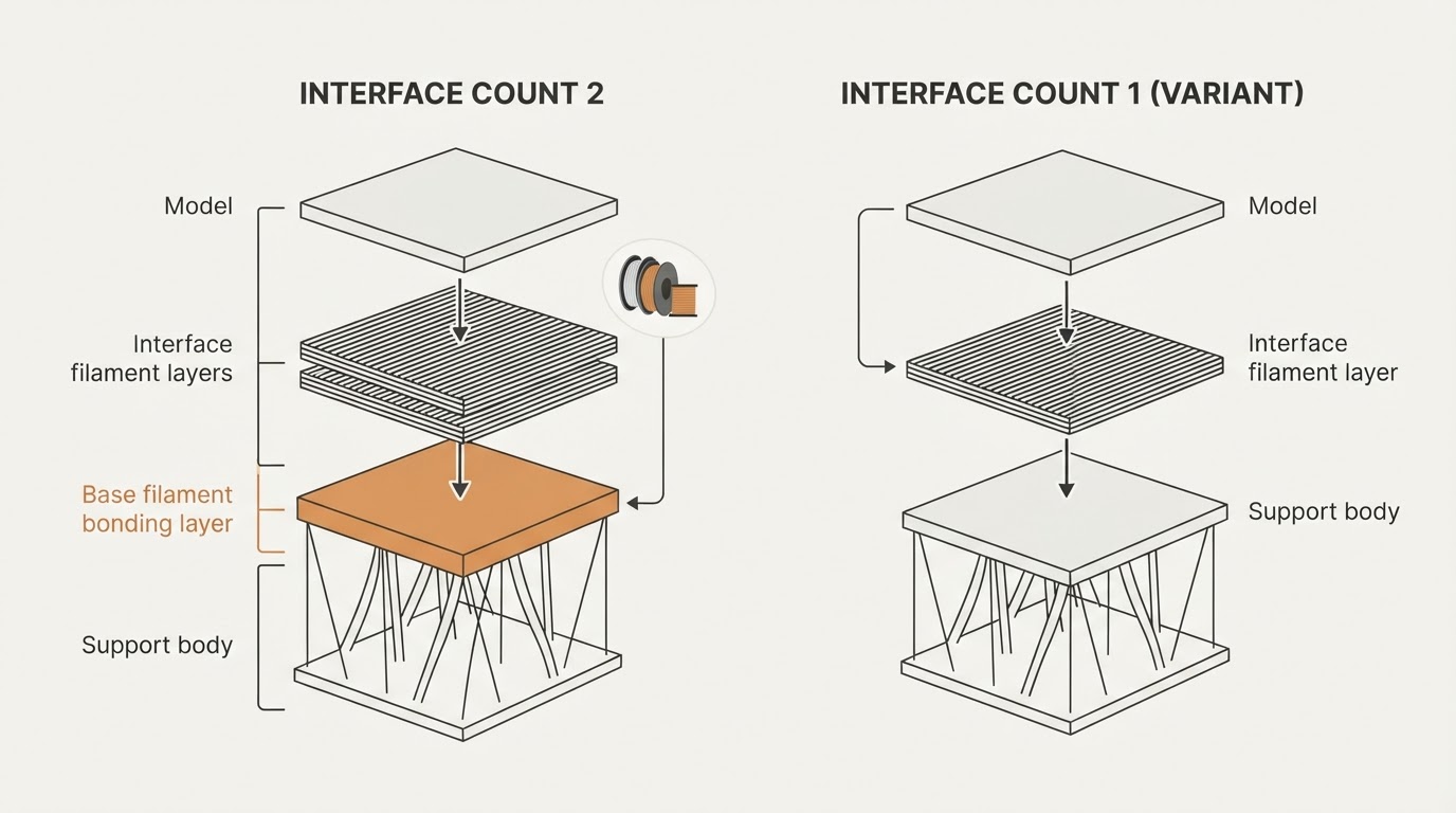
Support Cubic. Support Cubic is a variation of Cubic designed to support top layers. It uses more material than Lightning infill but is still a low-density pattern, so treat it as internal roof support rather than as the same thing as external supports.
The documentation also notes that Adaptive Cubic and Support Cubic do not support rotation: the sparse infill direction and the sparse infill rotation template are disabled for them, so leave those settings out of your comparison for those two patterns.
A Part-First Decision Table
If the part must... | Check first | Start with | Verify how |
|---|---|---|---|
Look good: cosmetic shell or visible top surface | Top shell thickness and the layers directly beneath it | Grid or Cubic as a predictable base under the top shell | Preview the layers under the visible skin and confirm consistent sparse support |
Take load from several directions | Wall count, orientation and the real load path | Gyroid, or Cubic / Adaptive Cubic as a starting point | Preview, print, then run a real mechanical check of the part |
Carry an internal top surface over a sparse cavity | The internal overhang and the layer just before the top shell | Support Cubic | Preview every layer under that roof and confirm material is concentrated there |
Decide what the part has to do first, then choose a pattern that supports that job, and then check the slice.
Check the Installed Version Before Relying on Non-Crossing Cubic
The strength settings documentation marks the non-crossing form of Cubic — the trapezoidal paths that avoid self-intersections when more than one line is used per infill wall — as a new feature available in nightly builds or in releases newer than 2.4.2. That qualifier belongs to that non-crossing path behavior, not to every infill setting: the pattern menu itself works on stable releases.
Do not assume your copy has the non-crossing form because the article is current: check the version of Orca Slicer you actually run. On an older stable build, Cubic can still behave as a plain crossing pattern, and the trapezoidal paths described in the documentation may not appear in your preview at all.
Keep a Blank Comparison Sheet
Hold everything except the pattern constant: same geometry, same orientation, same walls, same top and bottom settings, same material and profile, and the same requested density. Actual material usage can still differ between patterns because density is interpreted differently by each one, so record what the slicer reports instead of assuming it will match.
Pattern | Sparse % | Printer / nozzle / profile | Sliced time | Material mass | Top-surface support observations | Physical result (leave empty until tested) |
|---|---|---|---|---|---|---|
Grid |
|
|
|
|
|
|
Gyroid |
|
|
|
|
|
|
Cubic / Adaptive Cubic |
|
|
|
|
|
|
Support Cubic |
|
|
|
|
|
|
Fill the first six columns from the slicer and the preview; sliced time and material mass there are slicer estimates, not measurements of a finished part. Leave the physical result blank until you have run the part. If only one region of a model needs a different pattern, use a local modifier instead of changing the whole object. If time rather than structure is what you are trying to change, the Orca Slicer speed settings guide covers that side of the trade-off.
Preview Every Layer, Then Test
Slice once and step through the result in the preview. Check that the requested pattern actually appears in the sparse region, that the layers below each top surface are supported the way the table predicts, and whether the non-crossing form you expected is present in your build.
Sliced time and material mass are slicer estimates: useful for comparing configurations, not evidence of strength. No infill pattern guarantees a mechanically isotropic part; a physical test of the printed part, loaded the way it will be used, is the only thing that answers whether the combination of walls, shells, infill and material is strong enough for the job. Run that test on a calibrated machine — work through the Orca Slicer calibration order first, so the difference you are comparing comes from the infill rather than from an uncalibrated profile. Fill the last column only after the test.