What Orca Slicer ironing calibration actually changes
Ironing is a second pass over the top surface at the same layer height, printed with a very low flow rate and a dedicated pattern. The nozzle re-melts the topmost lines and presses material into the gaps, which is why a calibrated pass can turn a ridged top into a satin one. It is also why you cannot copy someone else's numbers: flow, speed, spacing and angle interact with your nozzle, layer height and filament, so the only trustworthy Orca Slicer ironing settings are the ones you test on your own machine.
The setting names below follow the official OrcaSlicer Ironing wiki. OrcaSlicer releases change, so confirm the labels in the version installed on your own machine. This is a procedure to run, not a claim that these example patches were printed or measured here.
Before the first patch: freeze everything except one variable
An Orca Slicer ironing test only means something if the prints are comparable. Freeze the machine state: same nozzle, layer height, filament spool and room conditions.
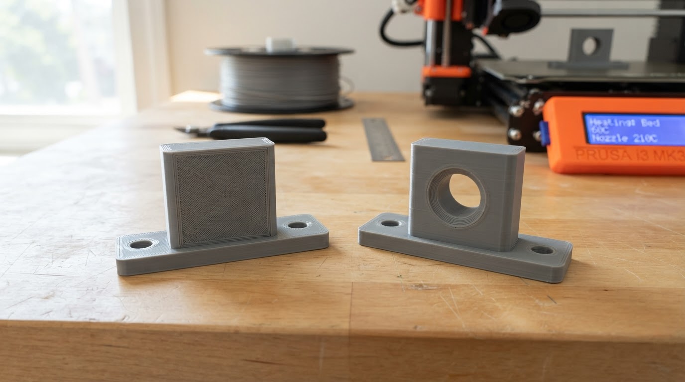
- Use a small flat patch, about 40 mm by 40 mm and 2 mm tall. If you download a parametric ironing calibration test from a model repository, take it from the original model page and read its licence before you share the STL or sliced files; some licences restrict derivatives.
- Give ironing a properly closed top surface. If the base print has gaps or under-extrusion, fix those before trying to hide them with ironing. The site's calibration order guide covers that earlier tuning work.
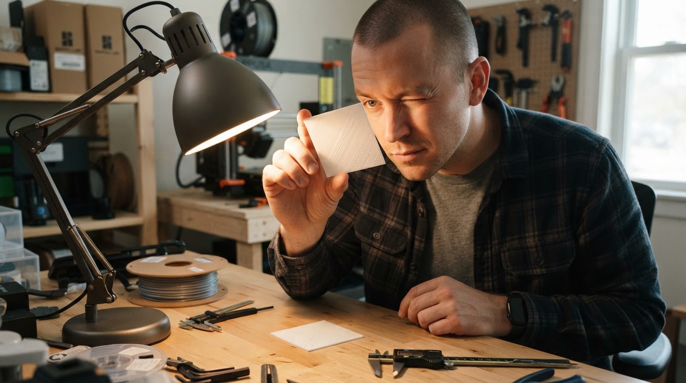
- Get raking light. Angle a desk lamp low over the bench so the surface catches the light; this is the difference between "looks fine" and "there are gaps between every line".
Step 1: the Orca Slicer ironing flow test
Ironing flow is the material extruded during the ironing pass, expressed as a percentage of the normal flow rate. The official wiki states the trade-off plainly: a lower value is smoother but may not cover the surface, while a higher value covers better and can over-extrude.
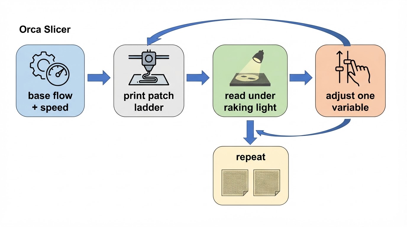
Start from the defaults in your working printer/material profile, record the actual flow and speed, then build a ladder without touching anything else:
Patch | Ironing flow | Speed | What the patch tests |
|---|---|---|---|
A | 75% of baseline | held constant | Coverage when material is scarce |
B | baseline | held constant | Your reference patch |
C | 125% of baseline | held constant | Extra coverage against smoothness |
D | 150% of baseline | held constant | The over-extrusion limit |
Print one patch per row and read coverage first, smoothness second. Under raking light, pinholes or gaps between the ironing lines may indicate too little material; ridges or blobs may indicate too much. Choose the lowest flow that gives even coverage and a good finish on your material; do not keep increasing flow just because a coupon looks filled.
Lower layer heights usually need a higher flow percentage, since there is less volumetric extrusion per distance travelled. If you change layer height later, run these rows again.
Step 2: the Orca ironing speed test
Speed decides how long the nozzle dwells on each line and how much heat it leaves behind. With flow frozen at the winner from step one, repeat the same method with a speed ladder at 75%, 100%, 125% and 150% of your baseline speed.
Judge each patch on evenness, visible pattern, edge behavior and corner curl. Slower passes leave more heat in the part; faster passes give the lines less time to fuse. Keep the fastest speed that stays even.
Step 3: spacing, inset and angle, still one at a time
- Line spacing: the official wiki recommends keeping it equal to or below the nozzle diameter for optimal coverage.
- Inset: a non-zero inset keeps the path away from the perimeter and helps prevent over-extrusion at the edges. Raise it in small steps until edge blobs disappear.
- Angle: offsets of 0, 45 and 90 degrees each finish differently; with the default 45 degree solid-infill direction, the documented fixed-angle suggestions are 0 and 90 degrees. If reflected light shows alternating bands, test the fixed angle.
Diagnostic matrix: read the surface, then change one thing
What you see under raking light | Change first | Leave alone |
|---|---|---|
Pinholes or gaps between lines | Flow up | Speed |
Visible comb or streak pattern | Angle offset | Flow |
Blobs, ridges, wet sheen | Flow down | Spacing |
Scratches or drag marks | Inspect nozzle contact, top-layer quality and flow before changing speed | Angle |
Over-extruded ridge at the outline | Inset up | Flow |
Alternating shiny bands across the top | Fixed angle | Spacing |
When the calibration is finished
The ironing calibration test is done when two consecutive patches stop improving and the surface stays even under raking light from two directions. Confirm on one real part with different geometry, since a flat coupon hides corner behavior. Re-run the ladder whenever you change nozzle, layer height or material, and save the result into the filament or printer profile so it survives the next spool.
Limitations worth taking seriously
- Heat creep. Ironing moves filament through the hotend slowly, and the official wiki warns this raises the risk of heat creep and clogging. Monitor the print and keep hotend cooling adequate.
- Large flat parts. The published guide warns against ironing huge flat surfaces, because the heat can distort them.
- Time. Ironing adds a second pass over the top, so it lengthens every print it touches.
- No universal numbers. A value that is perfect on a 0.4 mm nozzle at 0.2 mm layers is a starting point elsewhere, not an answer.
FAQ
Should I calibrate ironing flow or ironing speed first?
Flow. Coverage decides whether the surface is sealed at all; speed refines the finish afterwards. Changing both between patches hides which one caused the change.
Why does more flow make the surface worse?
Flow is a percentage of the normal flow rate, so past a certain point the extra material has nowhere to go. The surface turns rough or blobby even though the gaps closed earlier.
Does one calibration transfer to another 3D printer ironing calibration run?
Only as a starting point. Ideal flow depends on layer height and on how your hotend and nozzle lay material, so move the value with the profile and check a patch before trusting it on a display print.