What the Resolution Setting Changes
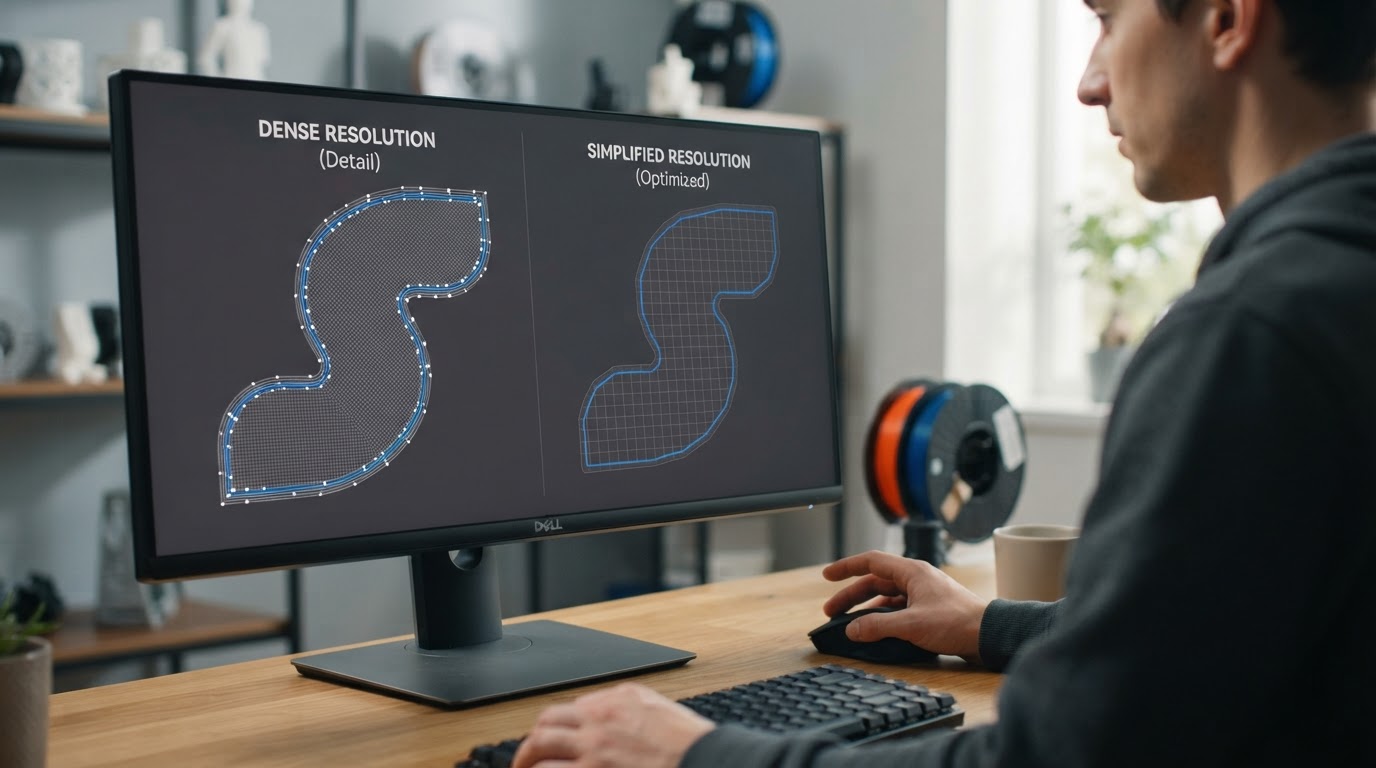
The Resolution setting is the contour-simplification step that runs before Orca Slicer writes toolpaths. The project wiki describes it as an Advanced-mode Float in the Quality settings' precision group, with the internal variable name resolution. Before G-code is generated, the slicer simplifies model contours so it does not carry an excessive number of points and lines. Smaller values keep more of the contour detail that is already in the mesh and add slicing time. Larger values simplify more aggressively, which the wiki suggests considering when slicing large models on a low-power machine.
Open the process profile you are actually printing, go to Quality, and look in the Precision group. If it is hidden, switch the visibility mode; the wiki marks it Advanced. The value is a slicing distance, not a description of the finished part.
For the current field label and wording, see the official OrcaSlicer precision settings page in the project wiki.
Resolution Is Not Layer Height
Layer height controls the vertical step between layers. Resolution works on the contour in the XY plane before those layers are filled. It does not directly set the vertical layer height, so lowering it will not thin layers or fix first-layer squish. Raising it will not thicken the part or change the shell count.
That says which control owns the vertical step; it does not mean curved surfaces are unaffected by contour handling. Stair-stepping on a curved top is mainly a layer-height outcome, while Resolution works on each slice's horizontal outline and can still change how a curve's edge is represented. Judge the two separately.
It is also not an accuracy specification. The value tells the slicer how much contour detail it may discard; it does not tell you what tolerance your printer, filament, and calibration will hold. If a hole or outside wall is the wrong size, that is dimensional work: Orca Slicer has separate X-Y hole and contour compensation controls, and the hole compensation guide explains their signs and a measurement routine. Treat Resolution as toolpath detail, not a substitute.
How to Choose a Value
There is no universal best number, and the right starting point is the value already in your process profile. Change one variable at a time and judge the result by the symptom you want to solve.
- Small features or curved walls lose their shape in Preview, or a fine engraved detail disappears: check the mesh first, then try a smaller value and expect a longer slice.
- Slicing a very large model stalls a low-power machine: a larger value can shorten the wait, at the cost of contour detail.
- The print has dimensional error or rough top surfaces: stop adjusting Resolution and diagnose those causes instead.
A smaller value can preserve detail already in the mesh, but it cannot recreate detail the mesh never had. If the STL was exported as a coarse cylinder, no Resolution value will restore the smooth curvature you expected; those facets are in the source geometry, so re-export at a finer tessellation and slice again. Resolution controls how much existing mesh detail survives simplification; it does not add curvature.
Do not copy a number from a settings list and assume it behaves the same on your model. The effect depends on the geometry, mesh polygon density, and process profile.
Arc Fitting Is Toolpath Encoding
Arc fitting sits in the same precision group but does a different job. When enabled, it replaces many short straight G1 moves with fewer G2 and G3 arc commands. The wiki is explicit that this changes toolpath encoding and is not a feature for improving print quality.
That matters for two reasons. First, the firmware must support G2 and G3; some firmware ignores them. Second, the wiki lists real trade-offs: arcs are an approximation, final smoothness depends on the firmware's arc segmentation, and arc processing can slow older 8-bit controllers. The current wiki also documents that arc fitting is not available on belt printers or while extrusion rate smoothing is enabled, but treat those as build-specific. Your installed build and firmware decide which fields appear, which commands are honored, and how arcs are turned back into segments, so verify them and confirm support before treating arc fitting as a quality upgrade.
Do Not Confuse It With Arachne Maximum Wall Resolution
Orca Slicer's Arachne wall generator has its own Maximum wall resolution control, which limits the smallest wall segment Arachne keeps while simplifying wall paths. It is a separate field with a separate job from the Quality > Precision Resolution setting, and changing it is not a substitute for changing Resolution. Its availability, visibility mode, and default value depend on the OrcaSlicer version and on the wall generator the profile uses, so do not carry a number or a label over from another build. When tuning wall behavior, change one control, re-slice, and read the Preview before touching the other.
A Controlled Re-Slice Check
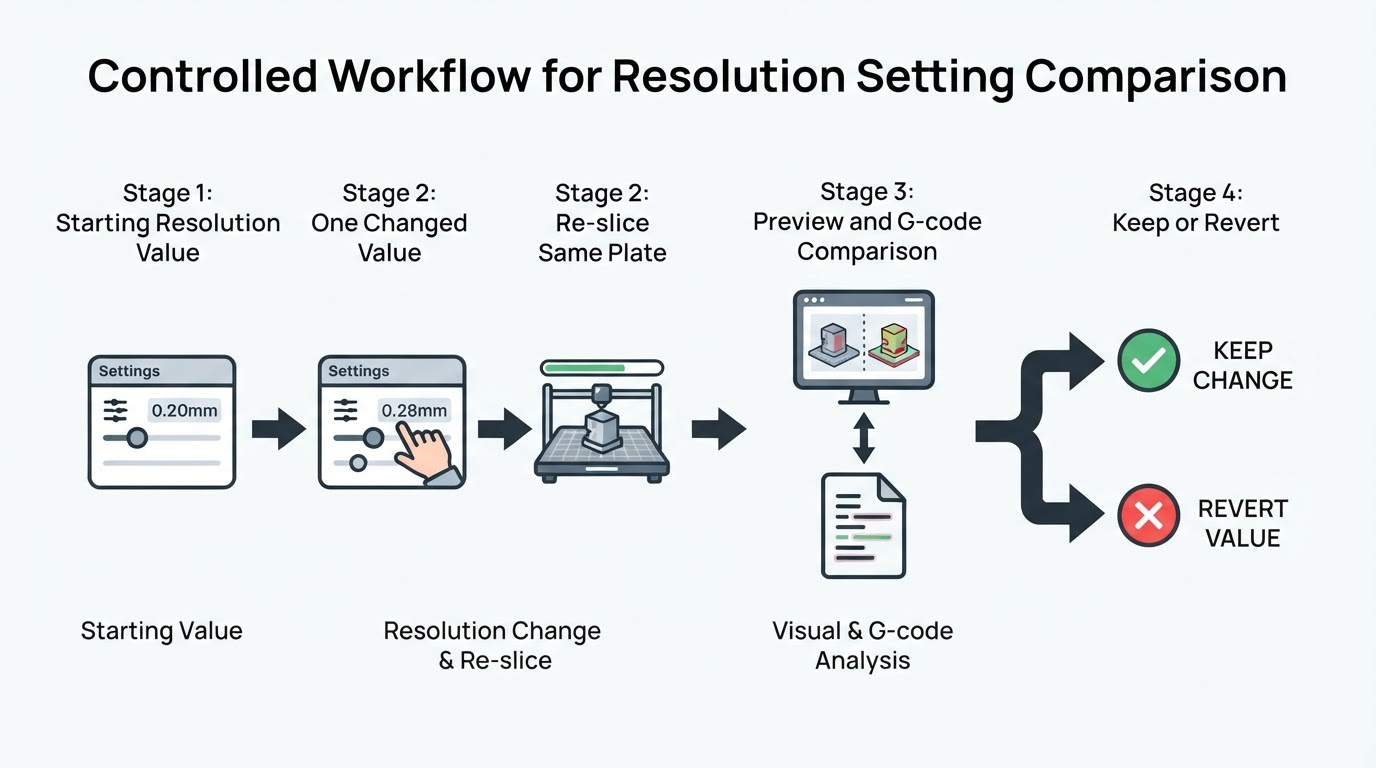
A useful check is proposed work, not a test result: no OrcaSlicer slice was run to produce this guide. Re-slice the same plate twice and compare what the slicer produced. Save the editable project first so both variants remain available; the save project vs export guide explains which command preserves the settings you need to repeat the check.
- Record the current Resolution value and the process profile name.
- Change only Resolution, then slice the same plate again.
- Compare the two Preview views at the same layer and zoom, then compare the G-code point or line counts.
- Write down the difference and the value you kept, plus the reason.
Observation | What it suggests | Next step |
|---|---|---|
Curves look faceted, fine detail missing | Contour simplified too aggressively, or the mesh itself is coarse | Compare the sliced contour with the mesh, then try a smaller value or a finer STL |
Slice time is excessive on a large model | Detail retention costs processing time | Try a larger value, then re-check Preview |
Dimensions are wrong, shape looks fine | Simplification may have altered a small feature, or the error may come from elsewhere | Inspect the mesh and the sliced toolpath for that feature before deciding whether compensation is appropriate |
A shape that looks right at one zoom level can still hide a shrunken boss, slot, or small hole, so do not use appearance alone to rule Resolution out. Check the mesh and toolpath for that feature before touching X-Y compensation.
The completion standard: you can explain what changed in the sliced output and know which value you are keeping. A Preview or G-code comparison shows slicing differences only; it does not prove how the printed part will measure or how strong it will be.