Where the controls are, and what they are called
Open the Process profile and go to the Speed section. OrcaSlicer's official documentation marks the relevant options as Advanced, so if the panel looks shorter than expected, switch the visibility control to Advanced. The master switch is labeled Slow down for overhang. The separate toggle is Slow down for curled perimeters. The speed values appear as four numeric fields, listed in the official Overhang Speed wiki page as overhang_1_4_speed through overhang_4_4_speed.
Control | Internal variable | Type | What it changes |
|---|---|---|---|
Slow down for overhang |
| Boolean | Master switch for overhang slowdown |
Slow down for curled perimeters |
| Boolean | Extra slowing in regions the slicer predicts are prone to perimeter curling |
Overhang speed, four fields |
| Float or percentage | Requested speed for each overhang range as the interface defines it |
Labels, grouping and defaults can move between OrcaSlicer releases, and a process preset can be saved for a different machine, nozzle or purpose than the one in front of you. Before tuning, confirm that the preset selected for the plate is the one you are editing, that you are in Process settings rather than Filament or Printer, and that the fields match the labels and tooltips in your build. Different labels do not by themselves mean a preset is damaged. Read what your version exposes, and make changes on a copy of the profile you trust.
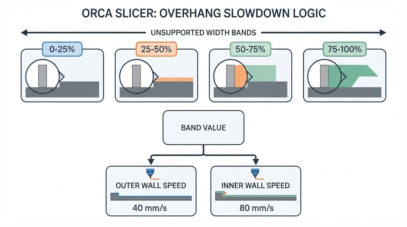
The percentage is unsupported line width, not model angle
The official page says overhang degrees are expressed as a percentage of line width, which is easy to read as if you were entering a model angle. It is not. The slicer examines a segment and the share of that segment's line width that has no material directly beneath it, then applies the field that covers that range. Nothing here is measured in CAD degrees.
The four variable names order the fields, but they do not publish the range boundaries, imply four equal bands, or define an interpolation rule. The labels and tooltips in your installed build define what each field covers, and those can change between versions. Do not infer an exact threshold from a suffix in a variable name.
The same percentage also resolves against a different reference depending on the wall: the wiki states that a percentage is calculated from outer wall speed for outer walls and from inner wall speed for inner walls. That is why one field value can produce two different requested speeds in the same print. For background on how requested speeds sit alongside flow, cooling and acceleration limits, see the OrcaSlicer speed settings guide.
mm/s versus percent, and what the arithmetic actually promises
Consider an outer wall speed of 120 mm/s and an inner wall speed of 160 mm/s, with 50% entered in one of the overhang speed fields. The requested speed for that range is 60 mm/s on an outer wall and 80 mm/s on an inner wall. Those are requests, not guarantees. Before the move reaches the nozzle, flow limits, cooling and minimum layer time, acceleration, and any other applicable limit can lower it. Whether the feature is eligible for the overhang rule at all can also change which value applies.
Enter 40 mm/s in the same field and the request is 40 mm/s for that range. That is still a request, not the speed the printer will necessarily deliver: the value passes through every other limit, and eligibility still matters. The field type is documented as float or percentage, and that is the real fork in behavior.
What you want | Enter | Reason |
|---|---|---|
Slowdown that moves when wall speed changes | Percentage | Follows the outer or inner wall speed for that wall |
A fixed upper request for this range | mm/s | Applied as an absolute value instead of derived |
A preset carried between printers with different wall speeds | Percentage | Wall speed changes carry the range with them |
A deliberate cap while isolating another problem | mm/s | Removes wall speed from the arithmetic |
Whichever you choose, do not treat the two as interchangeable during a comparison. Switching a field from a percentage to an absolute number is a real change to the requested speed, not a formatting preference.
Zero means "use wall speed here", not "slowest"
The wiki's note is short: 0 speed means no slowing down for the overhang range, and wall speed is used. Zero is an opt-out, not a maximum. If the master switch is on and every field is zero, the four overhang fields contribute no slowdown, but that does not guarantee that every overhang physically runs at normal wall speed. Curled-perimeter handling, bridge values, minimum layer time, cooling and acceleration limits can all still shape the move.
That is also the first thing to check when the preview disagrees with your intent. The preview shows the result after the rules that applied, so a segment may look fast because:
- the field for that range is zero, so wall speed is used;
- the segment was not in the range you assumed, because support loss is evaluated per line rather than per model feature;
- the wall is outer or inner and the percentage resolved against a different base than you expected.
If your build shows a per-segment speed at the cursor, read that number rather than judging by color. Speed color scales can differ between versions.
Curled perimeters: predicted from the path, not measured on the printer
Slow down for curled perimeters is a separate switch from the four speed fields. It is not a sensor reading perimeters that have already curled on the printer. The slicer predicts regions where perimeter curling is likely, using the toolpath and geometry, and adds slowdown there. The wiki gives the sharp front of the Benchy hull as an example, where curling compounds over successive layers. Its guidance is to leave the option on unless your cooling is powerful enough, or the print slow enough, that perimeter curling does not happen.
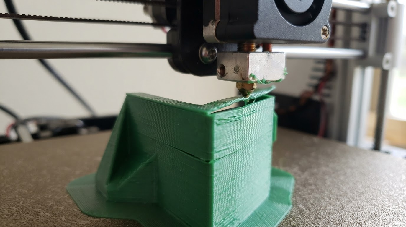
The wiki also warns that with a high external perimeter speed, this slowdown can create a large variance in print speed and produce wall artifacts when the extruder cannot keep up with the requested flow change. It attributes those artifacts most likely to pressure advance tuning that is slightly off. The official overhang speed documentation describes follow-up tuning for that situation. Treat it as advanced tuning on a copy of the profile and follow your machine's own documentation; this guide does not prescribe firmware or profile-protection changes.
The bridge interaction is conditional and worth knowing. When this option is enabled, the wiki notes that overhang perimeters are treated like overhangs even when they are part of a bridge. For example, a perimeter that is 100% overhanging uses the 75% overhang speed, capped at the external bridge speed. Two profiles that differ only in this toggle can show different speeds on bridge-adjacent walls even when every field value is identical.
Bridge controls are a separate system
Bridge speed is set separately for internal and external bridges. Internal bridge speed can be entered in mm/s or as a percentage of external bridge speed, with 150% as the documented default, and the wiki recommends raising internal bridge speed to save time while lowering external bridge speed for quality. The OrcaSlicer bridge settings guide covers diagnosing sagging and broken bridges before changing values.
The two systems meet in one documented case. When Slow down for overhang is on and Slow down for curled perimeters is off, external bridge speed also applies to overhang walls supported by less than 13% of their line width, and their speed blends from the 75% overhang speed toward external bridge speed as support drops to zero. A nearly floating wall can therefore be partly governed by a bridge value you never touched. If an edit at the extreme end of the range seems to do nothing, check bridge speed before editing the field again.
A reader check: slice first, change one value
This is a procedure to try, not a benchmark we ran. The point is to connect one field value to a visible segment before committing filament.
- Choose a small model with a suitable overhang, or a stepped coupon whose ledges lose support gradually, and slice it with your current profile.
- In the preview, find the region you care about and note the planned speed and which rule produced it.
- Change exactly one applicable overhang value, keep every other setting fixed, and re-slice. If you change several values at once, you cannot tell which one did anything.
- Compare the two previews. Preview speeds are slicer estimates, not measurements from your printer.
- Print the baseline and the changed version only if you want physical evidence. One coupon looking better or worse does not prove cause, and it does not prove a safe completion. Repeat the observation and consider material, cooling and geometry.
There is no universal overhang speed that suits every material and geometry, and the fields do not affect every eligible feature identically. The useful outcome is knowing which field covers the segment you are looking at, and what the preview says the slicer plans to do there.
Habits that prevent most overhang slowdown mistakes
- Confirm Advanced visibility, then read the labels and tooltips in your installed build.
- Keep the meaning straight: the percentage is the unsupported share of line width, not a model angle.
- Treat zero as an opt-out for that range, not as the slowest setting.
- Change one applicable value at a time and hold the rest fixed.
- Remember that curled-perimeter and bridge rules can change the result independently of the four fields.
- Read preview speeds as plans, not as printer measurements.